

Inductor#
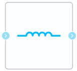
Block appearance in REPEAT VISION#
The Inductor block implements an ideal inductor model described by the following expression (1):
where \(L\) - inductance of the coil, [H].
The positive direction of current in the inductor is defined as flowing from the input port to the output port. The voltage across the inductor is determined as the potential difference between the input and output ports.
1. Properties#
Property |
Default Value |
Description |
Units of measurement |
|---|---|---|---|
Inductance |
0.001 |
– |
H |
Initial current |
0 |
– |
A |
2. Inputs and outputs#
Parameters |
Input/Output |
Description |
Units of measurement |
Port type |
|---|---|---|---|---|
+ |
Input |
– |
– |
Electronics |
- |
Output |
– |
– |
Electronics |
In order to see the connection capabilities of the block, you need to go to page Description of block ports
3. Examples of use#
Examples of using this block can be found in the following sections:
Description of Demo.
Tutorials
Library |
Tutorial name |
|---|---|
Electronics |
Inductance in AC circuit; |
How-to guides
Section |
Guide name |
|---|---|
Electrical equipment / Power industry |
Implementation of DC insert and harmonic analysis of electric power system currents; |