

Three-phase transmission line (positive- and zero-sequence parameters)#
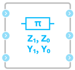
Block appearance in REPEAT VISION#
Three-phase transmission line (positive- and zero-sequence parameters) block implements a mathematical model of three-phase power transmission line (PTL) with lumped parameters in accordance with U-shaped equivalent circuit, which is given in Fig. 1.
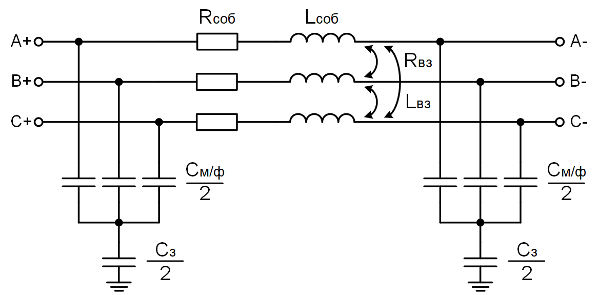
Fig. 1 U-shaped equivalent circuit of three-phase PTL with lumped parameters#
Note
The block does not set the parameters of the equivalent circuit directly, but the parameters of the direct and zero sequences, the base frequency and the section length, based on which the necessary values are calculated, taking into account the uniform distribution of parameters along the {term} ‘PTL’. This form of setting parameters makes it possible to take into account the mutual active resistances, inductances and capacitances of the three-phase PTL, without directly specifying values of 3x3 matrix for each parameter. For more information on converting parameter matrices into values of the direct and zero sequences, see additional literature [1].
Important
To obtain a more detailed voltage distribution curve along the PTL, it is necessary to divide the line into several sections, each of which is modeled by this block.
Fig. 1 shows the following equivalent circuit parameters:
\(R_{own}\) – own effective resistance of phase wire, reflecting heat losses;
\(L_{own}\) – phase wire intrinsic inductance reflecting conductor self-induction;
\(R_{mt}\) – mutual effective resistance of the phase wire;
Note
This value has no physical meaning and appears when non-zero effective neutral resistance is excluded from the equivalent circuit.
Note
If the phase parameters of the mode are of greatest interest in the calculation process, the effective resistance of the neutral can be taken equal to 0. In this case, one shall specify the same resistance values in the Positive- and zero-sequence active resistance per unit length property.
\(L_{mt}\) – mutual inductance of phase wire reflecting mutual inductance between phase wires;
\(C_{b/p}\) – capacity between phases PTL, which causes displacement currents between phase wires;
\(C_g\) – capacity between phase wire and ground, which causes leakage currents to ground.
The procedure for calculating the parameters of the positive and zero sequences for the equivalent circuit of a power transmission line is described in the article “The procedure for calculating the specific parameters of three-phase power transmission line models”
Equivalent circuit parameters are calculated from user-defined linear parameters for direct and zero sequences using the formulas (1), (2) and (3) :
where \(R_1, R_0, L_1, L_0, C_1, C_0\) are calculated parameters of direct and zero sequences taking into account line length and uniform distribution of parameters along the line.
Note
When setting block parameters, it is not recommended to set the same capacitance values in the Positive- and zero-sequence capacitance per unit length property, since in this case, in (3) formula, the denominator of the expression can be 0 with certain values of other parameters.
The block approximately takes into account the uniform distribution of line parameters along the length according to the formulas (4), (5), (6), (7), (8), (9) и (10)[2] for each individual sequence:
where:
r, l, c – linear values of effective resistance, inductance and capacitance;
\(w=2\cdot \pi \cdot f\) – angular frequency, which is calculated for \(f\) base frequency specified by the user;
\(z, y\) – linear complex series resistance and transverse conductivity;
\(Z_w\) – wave resistance;
\(\gamma\) – constant distribution;
\(L_{PTL}\) is the line length set by the user;
\(R, L, C\) – values of effective resistance, inductance and capacitance taking into account their uniform distribution along the line length.
Note
When setting block properties, check the phase velocity value \(v_w=\frac{1}{l\cdot c}\)[3]. The maximum value of this parameter is 300,000 [km/s], if this value is exceeded, the modeling results are not guaranteed to be correct.
&Emsp;parameters \(R, L, C\) calculated as per the formulas (4), (5), (6), (7), (8), (9) and (10) will be correct when the supply network frequency is close to Base Frequency. If the network frequency deviates significantly, it is recommended to specify the value of the corresponding property.
1. Properties#
Property |
Default Value |
Description |
Units of measurement |
|---|---|---|---|
50.0 |
- |
Hz |
|
Section length |
100.0 |
- |
km |
Positive- and zero-sequence active resistance per unit length: |
0.301; |
- |
Ohm/km |
Positive- and zero-sequence inductance per unit length: |
0.00134; |
- |
H/km |
Positive- and zero-sequence capacitance per unit length: |
8.62e-9; |
- |
F/km |
2. Inputs and outputs#
Parameters |
Input/Output |
Description |
Units of measurement |
Port type |
|---|---|---|---|---|
A+ |
Input |
- |
- |
Electronics |
B+ |
Input |
- |
- |
Electronics |
C+ |
Input |
- |
- |
Electronics |
A- |
Output |
- |
- |
Electronics |
B- |
Output |
- |
- |
Electronics |
C- |
Output |
- |
- |
Electronics |
In order to see the connection capabilities of the block, you need to go to page Description of block ports