

Needle valve (TL)#
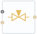
Block appearance in REPEAT VISION#
The block describes the flow of isothermal liquid through a needle valve, in which the needle closes the hole for the flow of liquid when seated in the seat.
The amount of valve opening (needle raising) displacement is given by the sum of the external signal S and needle displacement Needle offset in the closed position of the valve.
When the valve is closed (
displacement<0), the flow area is equal to the leak area.When
displacement>Seat diameter(displacement of the needle exceeds the diameter of the valve seat), the flow area is unchanged and maximum.
The block can use smoothing option when the Smoothing factor is>0 for the displacement parameter at extreme positions (comparable to 0 or Seat diameter).
Also, the block can use the pressure recovery option - to enable it, set the parameter value Pressure recovery - On
The opening area of the valve is calculated as (1):
where:
\(h\) — is the vertical distance between the needle outer edge and the seat, as indicated in the circuit above;
\(θ\) — is the angle of the seat cone, which always corresponds to the angle of the needle cone;
\(d_0\) — diameter of seat hole;
\(A_{leak}\) - leakage area.
The hole area is limited by the maximum offset \(h_{max}\) (2):
For any needle displacement greater than \(h_{max}\) , \(A\) open is the sum of maximum opening area and leakage area (3):
For any combination of signal at port S and needle displacement less than 0, the minimum valve area is the leakage area.
The mass is retained by the valve:
\(\dot m_{A} + \dot m_{B} = 0\)
The mass flow rate through the valve is calculated as (4):
where: \(C_d\) – discharge coefficient;
\(A_{valve}\) - instantaneous open area of the valve;
\(A_{port}\) - is the cross-sectional area of ports A and B;
\(ρ\) – average density of liquid;
\(Δp\) – pressure difference on valve \(p_A\) – \(p_B\).
The critical pressure drop, \(Δp_{crit}\), is the pressure drop related to Critical Reynolds number, \(Re_{crit}\), the transition point of the flow mode between laminar and turbulent flow (5):
The pressure loss describes a decrease in pressure in the valve due to a decrease in area. PR loss is calculated as (6):
Pressure recovery describes a positive pressure change in the valve due to area increase. If you do not want to record this pressure increase, remove Pressure recovery flag. In this case, \(PR_{loss}\) is 1.
Law of conservation of energy
where:
\(\phi_A\) - energy flow at the input, [W];
\(\phi_B\) - energy flow at the output, [W].
1. Properties#
Property |
Default value |
Description |
Units of measurement |
|---|---|---|---|
Off |
- |
- |
|
0.3 |
- |
m |
|
Cone angle |
90.0 |
- |
degrees |
0.0 |
- |
m |
|
Leakage area |
1.0e-5 |
- |
m\(^2\) |
Port area |
0.07 |
- |
m\(^2\) |
Discharge coefficient, available when selecting |
0.64 |
- |
- |
150.0 |
The Reynolds number at which the transition from laminar to turbulent flow occurs |
- |
|
0.01 |
- |
- |
2. Inputs and outputs#
Parameters |
Input/Output |
Description |
Units of measurement |
Port type |
|---|---|---|---|---|
Auto |
Input |
- |
m |
Automation |
Input |
Input |
- |
- |
Thermohydraulics |
Output |
Output |
- |
- |
Thermohydraulics |
In order to see the connection capabilities of the block, you need to go to page Description of block ports