

Local resistance (TL)#
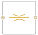
Block appearance in REPEAT VISION#
Local resistance (TL) unit simulates pressure loss due to user-defined pipe resistances in the thermal hydraulic network.
Hint
You can specify different loss factors for forward and reverse flows through a pipe segment.
The loss factor is parameterized either by a constant relationship based on pipe pressure or by user-provided tabular data for loss factors based on Reynolds number.
1.Loss coefficient
a) Constant loss coefficient
Segments with loss factors that remain constant over a range of flow rates are calculated as (1):
where:
\(k_{loss,AB}\) and \(k_{loss,BA}\) — parameters of forward flow loss factor (from A to B) and return flow loss factor (from B to A), respectively.
\(Δp\) – pressure difference \(p_A\) – \(p_B\), [Pa].
Critical pressure differential, \(Δp_{crit}\), is the pressure differential associated with the critical Reynolds number, \(Re_{crit}\), which is the transition point of the flow condition between laminar and turbulent flow (2):
where:
\(k_{loss,crit}\) — is the loss coefficient associated with critical pressure, which is based on the average of the forward and reverse loss factors;
\(v\) - liquid kinematic viscosity, [m\(^2\)/s];
\(ρ\) – average liquid density, [kg/m\(^3\)];
\(Dh\) – hydraulic diameter of the segment, [m], which is the equivalent diameter of the non-circular pipe \(D_{h}\:=\:\sqrt{\frac{4\:A_{flow}}{\pi}}\);
\(A_{flow}\) — flow area, [m\(^2\)].
b) Loss coefficient table
The loss factor may alternatively be interpolated based on user-provided Reynolds numbers and loss factor data. A vector of Reynolds numbers can have both positive and negative values, indicating forward and backward flow, respectively (3):
2. Mass flow rate calculation
Law of conservation of mass (4):
The mass flow rate through the resistance is calculated as (5):
where \(k_loss\) is the flow loss factor that is chosen between the forward flow loss factor (A to B) and the reverse flow loss factor (B to A) depending on the flow direction of the unit.
3. Energy balance
Law of conservation of energy (6):
where:
\(\phi_А\) - energy flow at the input, [W];
\(\phi_В\) - energy flow at the output, [W].
1. Properties#
Property |
Default value |
Description |
Units of measurement |
|---|---|---|---|
Method of loss calculation: |
Constant coefficients |
- |
- |
Straight flow loss coefficient, available when selecting |
1.0 |
- |
- |
Reverse flow loss coefficient, available when selecting |
1.0 |
- |
- |
Reynolds numbers vector, available when selecting |
-500.0;-200.0;-100.0;-50.0;-40.0;-30.0; |
- |
- |
Loss coefficient vector, available when selecting |
0.65;0.75;0.9;1.15;1.35;1.65; |
- |
- |
Pressure drop vector, available when selecting |
1272.0;3000.0;4128.0; |
- |
Pa |
Mass flow vector, available when selecting |
0.105;0.175;0.21; |
- |
kg/s |
Flow area |
0.2 |
- |
m\(^2\) |
Critical Reynolds number |
150.0 |
The Reynolds number at which the transition from laminar to turbulent flow occurs |
- |
2. Inputs and outputs#
Parameters |
Input/Output |
Description |
Units of measurement |
Port type |
|---|---|---|---|---|
Input |
Input |
- |
- |
Thermohydraulics |
Output |
Output |
- |
- |
Thermohydraulics |
Loss coefficent (straight flow) |
Input |
Available when selecting |
- |
Automation |
Loss coefficent (reverse flow) |
Input |
Available when selecting |
- |
Automation |
In order to see the connection capabilities of the block, you need to go to page Description of block ports
3. Examples of use#
Examples of using this block can be found in the following sections:
Description of Demo.
Tutorials
Library |
Tutorial name |
|---|---|
|
Study of the effect of hydraulic resistance when mixing flows of different temperatures |
How-to guides
Section |
Guide name |
|---|---|
Energy |
Development of a model of the industrial circuit system of oil coolers of NPP with WCWR |