

Voltage meter#
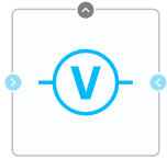
Block appearance in REPEAT VISION#
The Voltage meter block is designed to find the potential difference between two nodes to which the block is connected. The resulting voltage is found as follows (1):
Connection to the input ports + and - should be made from the Node blocks of the Electronics section. The output port Voltage is intended for connecting blocks of the Automation section and processing a signal equal to the measured voltage.
1. Inputs and outputs#
Parameters |
Input/Output |
Description |
Units of measurement |
Port type |
|---|---|---|---|---|
+ |
Input |
– |
– |
Electronics |
- |
Input |
– |
– |
Electronics |
Output |
– |
V |
Automation |
In order to see the connection capabilities of the block, you need to go to page Description of block ports
2. Examples of use#
Examples of using this block can be found in the following sections:
Description of Demo.
Tutorials
Library |
Tutorial name |
|---|---|
Electronics |
DC circuit; |
How-to guides
Section |
Guide name |
|---|---|
Electrical equipment / Power industry |
Simulation of static synchronous compensator based on voltage converter; |