

Confuser / Area Change (TL)#
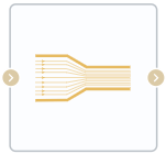
Block appearance in REPEAT VISION#
The Confuser / Area Change (TL) block describes the corresponding types of local resistances in a pipeline for a thermal-hydraulic system.
For a confuser, when fluid moves from the inlet port to the outlet port, the cross-sectional area of the flow narrows, and the fluid velocity increases; for reverse flow, it expands. For an area change (diffuser), the opposite occurs.
Hint
The cross-sectional areas can be set equal—in this case, the block will function as a local resistance with a constant diameter.
The loss coefficients for the block can be set empirically or via a tabular method.
For calculation based on empirical data:
For gradual conical contraction in the range of 0 to 45 degrees, the friction coefficient is calculated as (1):
where R - is the ratio of the smaller port area to the larger port area.
For contraction from 45 to 180 degrees (exclusive) (2):
For contraction at 180 degrees (3):
For gradual conical expansion in the range of 0 to 45 degrees, the friction coefficient is calculated as (4):
For expansion from 45 to 180 degrees (inclusive) (5):
For calculation based on tabular data, vectors of loss coefficients for contraction and expansion are assigned in accordance with the Reynolds number vector. All three vectors are set by the user as model parameters.
The total hydraulic loss coefficient for a pipe section with a diffuser is calculated as (6):
where:
\(\dot m_{A}\) - mass flow rate at the inlet port, [kg/s];
\(\dot m_{th}\) - threshold mass flow rate, [kg/s], at which a change in fluid flow direction occurs, related to the critical Reynolds number (7):
where:
\(A_{R}\) - area of the smaller of the two cross-sections, [m\(^2\)];
\(ν\) - kinematic viscosity of the fluid, [m/s\(^2\)];
\(\barρ\) - average fluid density, [kg/m\(^3\)];
\(D_{h}\) - diameter corresponding to the smallest cross-sectional area \(A_{R}\), calculated as (8):
The pressure drop across the pipe section with a diffuser is calculated as follows (9):
where (10):
Law of Conservation of Mass (11):
Law of conservation of energy (12):
where:
\(\phi_A\) - energy flow at the input, [W];
\(\phi_B\) - energy flow at the output, [W].
1. Properties#
Property |
Default Value |
Description |
Units of measurement |
|---|---|---|---|
Calculation method: |
Empirical |
- |
- |
Contraction loss coefficient, available when selecting |
1.0 |
- |
- |
Expansion loss coefficient, available when selecting |
1.0 |
- |
- |
Critical Reynolds number, available when selecting |
150.0 |
The Reynolds number at which the transition from laminar to turbulent flow occurs |
- |
Angle, available when selecting |
30.0 |
- |
deg |
Bigger area (port A) |
0.02 |
- |
m\(^2\) |
Smaller area (port B) |
0.01 |
- |
m\(^2\) |
Reynolds numbers vector, available when selecting |
{10,20,30,40,50,100,200,500,1000,2000} |
- |
- |
Contraction coefficient vector, available when selecting |
{5,2.7,1.8,1.46,1.3,.9,.65,.42,.3,.2} |
- |
- |
Expansion loss coefficient vector, available when selecting |
{3.1,2.3,1.65,1.35,1.15,.9,.75,.65,.55,.45} |
- |
- |
2. Inputs and outputs#
Parameters |
Input/Output |
Description |
Units of measurement |
Port type |
|---|---|---|---|---|
Input |
Input |
- |
- |
Thermohydraulics |
Output |
Output |
- |
- |
Thermohydraulics |
In order to see the connection capabilities of the block, you need to go to page Description of block ports