

Gate valve (P)#
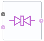
Block appearance in REPEAT VISION#
The Gate valve (P) block simulates changes in energy and pressure of a gas when passing through the component of pneumatic system - a gate valve that blocks the flow by moving (deltaL) the circular gate, which is set by sum of external signal S and gate offset in the closed position. The S signal increase causes the gate opening, and with S = 0 and gateOffset = 0 the gate is completely closed (1):
At \(\Delta\)L=0, the valve is completely closed; when the value of this parameter is increased, it opens.
At \(\Delta\)L≤0, the flow area is equal to the leakage area.
At \(\Delta\)L>d\(_0\), (gate displacement exceeds valve diameter), the flow area is unchanged and maximum.
The block can use smoothing option when Smoothing factor parameter is > 0 for the \(\Delta\)L parameter at extreme positions (comparable to 0 or d\(_0\), where d\(_0\) is hole diameter in the valve).
The pressure recovery option can also be used in the block - in order to connect it, set the parameter Pressure Recovery to On.
The area open to the flow at gate retraction is equal to (2):
where d\(_{0}\) - the diameter of the valve hole.
The area shielded by the gate valve in a partially open valve is equal to (3):
where \(\Delta\)l - is the gate displacement, which is the sum of signal at portSandgate position when the hole is fully closed.
If the displacement exceeds the diameter of the hole, the flow area is the sum of the maximum hole area and the leakage area (4):
For any combination of signal at port S and gate displacement is less than 0, the minimum valve area is theleakage area.
Mass flow calculation
The block calculates the mass flow rate as (5):
where:
\(C_d\) – discharge coefficient;
\(S_r\) – area of the hole, [m\(^2\)];
S — cross-sectional area of ports A and B, [m\(^2\)];
\(\rho\) – gas density, [kg/m\(^3\)];
p - gas pressure, [Pa]
\(\gamma\) - the adiabatic index.
Linearization of the equation for \(\frac{p_{out}}{p_{in}}\)>B\(_{lam}\) (6):
When the pressure ratio is less than the ratio \(\frac{p_{out}}{p_{in}}\) < \((\frac{2}{\gamma +1})^\frac {\gamma}{\gamma-1}\) the equation assumes (7):
Energy conservation law (8):
where:
\(\phi_А\) - energy flow at the input, [W];
\(\phi_В\) - energy flow at the output, [W].
1. Properties#
Property |
Default value |
Description |
Units of measurement |
|---|---|---|---|
Off |
- |
- |
|
Orifice diameter |
0.03 |
- |
m |
Leakage area |
1.0e-10 |
- |
m\(^2\) |
Area port |
0.07 |
- |
m\(^2\) |
Discharge coefficient, available when |
0.64 |
- |
- |
0.01 |
- |
- |
|
Laminar flow pressure ratio |
0.999 |
- |
- |
2. Inputs and outputs#
Parameters |
Input/Output |
Description |
Units of measurement |
Port type |
|---|---|---|---|---|
Normal gate offset |
Input |
- |
m |
Automation |
Input |
Input |
- |
- |
Pneumatics |
Output |
Output |
- |
- |
Pneumatics |
In order to see the connection capabilities of the block, you need to go to the Description of block ports page Description of blocks ports