

Solenoid (IH)#
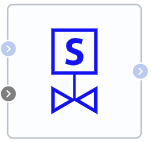
Block appearance in REPEAT VISION#
The Solenoid (IH) block simulates the operation of the corresponding component in a hydraulic network, which operates according to the following principle:
In addition to two standard hydraulic ports (input and output), the block has a control port by means of an automation signal receiving values in the range [0; 1]. If the signal is greater than or equal to 0.5, then the valve (solenoid) begins to gradually open, otherwise close. In this case, the current position, and with it the flow cross-sectional area, depend on the properties of the block specified by the user:
Valve initial positioncan beOpenandClosedand describes the state of the valve prior to calculation;Open time(\(t_{Open}\)) andClose time(\(t_{Close}\)) determine the rate of change of its position when moving in one direction or another;Maximum valve areareflects the maximum solenoid capacity when fully open.
Note
The nature of opening and closing the valve is linear, that is, the speed of movement of the control element does not depend on the time and current position.
Calculation of valve cross-sectional area:
When it is opened, the valve cross-sectional area \(A_{valve}\) is defined as (1) :
When it is closed, the valve cross-sectional area \(A_{valve}\) is defined as (2) :
where:
\(A_{init}\) is the initial valve area, [м\(^2\)], which, at the start of calculation from the zero moment of the model time, takes the value determined by Valve initial position property - either \(A_{max}\) (he valve is completely open), or 0 (the valve is completely closed). In case of shutdown and subsequent continuation of the calculation, \(A_{init}\) takes the last calculated value;
\(t_{Open}\) – valve opening time, [s];
\(t_{Close}\) – valve closing time, [s];
\(A_{max}\) – maximum valve area, [m$^2];
\(A_{leak}\) – leakage area, [m\(^2\)].
Law of mass conservation(3) :
where \(m_1\) and \(m_2\) is flow rate at block input and output, [kg/s].
Dependence of mass on pressure drop(4) :
where:
\(A_{valve}\) – solenoid cross-sectional area, [m\(^2\)];
\(A_{port}\) – port cross-sectional area, [m\(^2\)];
\(PR_{loss}\) – dimensionless loss factor;
\(\Delta p_{crit}\) – critical pressure drop, [Pa];
\(\Delta p\) – pressure drop between input and output port, [Pa].
Note
Calculated in the model core at each cycle of its operation
Calculation of critical drop(5) :
where:
emsp;\(C_d\) – Discharge coefficient;
\( u\) – liquid kinematic viscosity, mm\(^2\)/s;
\(Re_{crit}\) – Critical Reynolds numbers, the boundary between laminar and turbulent flow.
Calculation of loss ratios (6) :
Note
If Pressure recovery block property is set by the user to On position, \(PR_{loss}\) parameter takes the value 1 (with no size).
1. Properties#
Property |
Default Value |
Description |
Units of measurement |
|---|---|---|---|
Valve initial position: |
Closed |
- |
- |
0.05 |
- |
s |
|
0.1 |
- |
s |
|
1.0E-4 |
- |
m\(^2\) |
|
Leakage area |
1.0E-10 |
- |
m\(^2\) |
0.09 |
- |
m\(^2\) |
|
Discharge coefficient, available when selecting |
0.64 |
- |
- |
150.0 |
- |
- |
|
Off |
- |
- |
2. Inputs and outputs#
Parameters |
Input/Output |
Description |
Units of measurement |
Port type |
|---|---|---|---|---|
Input |
Input |
- |
- |
Isothermal Hydraulics |
Signal from 0 inc to 1 inc |
Input |
- |
- |
Automation |
Output |
Output |
- |
- |
Isothermal Hydraulics |
In order to see the connection capabilities of the block, you need to go to page Description of block ports