

Current-controlled switch (SPICE W)#

Block appearance in REPEAT VISION#
The Current-controlled switch (SPICE W) block implements a model of a switching device whose resistance between ports + and - depends on the control current \(I_c\) flowing from port C+ to port C-.
Note
The control ports C+ and C- must be connected in series to the branch whose current is used to control the switch. The connection is similar to the connection of the Current meter block.
The resistance of the switch can change smoothly or with hysteresis depending on the value of the Switching mode property.
Switching mode Smooth transition – in this mode, the turn-on current ION and turn-off current IOFF are set. Fig. 1 shows the dependence of the switch resistance \(R_s\) on the control current \(I_c\) for this mode.
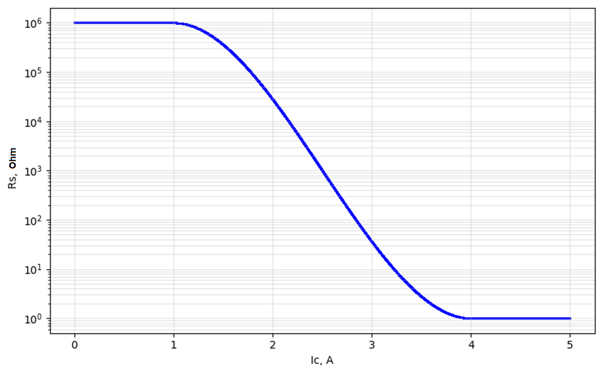
Fig. 1 Dependence of \(R_s\) on \(I_c\) in smooth switching mode (RON = 1 [Ohm], ROFF = 1000 [kOhm], ION = 4 [A], IOFF = 1 [A])#
The resistance of the key is determined as follows:
For the case when ION > IOFF:
if \(I_c\) ≥ ION, then \(R_s\) = RON (the switch is closed);
if \(I_c\) ≤ IOFF, then \(R_s\) = ROFF (the switch is open);
if IOFF < \(I_c\) < ION, then the resistance of the switch is determined by the formula (1) :
where:
\(L_m=ln(\sqrt{RON \cdot ROFF})\) – average logarithmic value of the key resistance, [Ohm];
\(L_r=ln(\frac{RON}{ROFF})\) – logarithmic ratio of the key resistances, [Ohm];
\(I_m=\frac{ION+IOFF}{2}\) – average value of on-off currents, [A];
\(I_d=ION-IOFF\) – difference between on- and off-currents, [A].
For the case when ION < IOFF:
if \(I_c\) ≤ ION, then \(R_s\) = RON (the switch is closed);
if \(I_c\) ≥ IOFF, then \(R_s\) = ROFF (the switch is open);
If IOFF > \(I_c\) > ION, then the resistance of the switch is also determined by the formula (1).
Note
In this mode, it is not recommended to make the zone between ION and IOFF too narrow.
Switching mode Hysteresis – in this mode, the threshold current IT and the hysteresis current IH are set. Fig. 2 shows the dependence of the switch resistance \(R_s\) on the control current \(I_c\) for this mode.
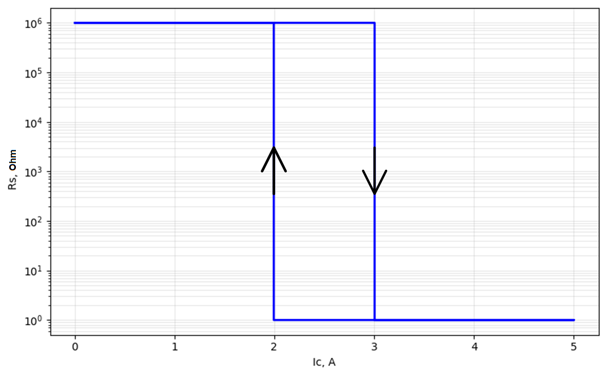
Fig. 2 Dependence of \(R_s\) on \(I_c\) during switching with hysteresis (RON = 1 [Ohm], ROFF = 1000 [kOhm], IT = 2.5 [A], IH = 0.5 [A])#
The resistance of the key changes according to the law:
if \(I_c\) ≥ IT + IH, then \(R_s\) = RON (the key is closed);
if \(I_c\) < IT - IH, then \(R_s\) = ROFF (the switch is open);
if none of the above conditions are met, then the state of the key remains the same as it was in the previous calculation step.
1. Properties#
Property |
Default Value |
Description |
Units of measurement |
|---|---|---|---|
Switching mode: |
Smooth transition |
– |
– |
RON – on resistance |
1.0 |
– |
Ohm |
ROFF – off resistance |
1e6 |
– |
Ohm |
ION – control current for on state |
1е-3 |
Available, when |
А |
IOFF – control current for off state |
0.0 |
Available, when |
А |
IT – threshold current |
0.0 |
Available, when |
А |
IH – hysteresis current |
0.0 |
Available, when |
А |
2. Inputs and outputs#
Parameters |
Input/Output |
Description |
Units of measurement |
Port type |
|---|---|---|---|---|
+ |
Input |
- |
- |
Electronics |
C+ |
Input |
- |
- |
Electronics |
- |
Output |
- |
- |
Electronics |
C- |
Output |
- |
- |
Electronics |
In order to see the connection capabilities of the block, you need to go to page Description of block ports