

Longitudinal movement with Preset Pitch Angle#
Block appearance in REPEAT VISION#
Consider the longitudinal controlled motion in the starting coordinate system, which is denoted 0xyz to reduce indexing. Suppose that the roll and yaw control ensures the flight of the missile in a vertical plane passing through the launch site and target. It can be assumed that the forces applied to the rocket operate in the same plane - in the firing plane, and the flight path is a flat curve (see Fig. 1 below).
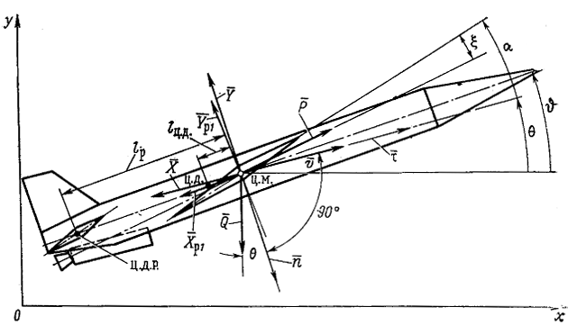
Figure 1. Diagram of force action on projectile aircraft moving during starting engine operation#
Components of forces acting on the projectile aircraft along axes τ and n
Force |
Tangential component (projection on the τ axis) |
Normal component (projection on the n axis) |
|---|---|---|
Thrust force |
P\(\cdot\) cos(\(\alpha - \xi \)) |
-P\(\cdot\) sin(\(\alpha - \xi \)) |
Drag |
-X |
- |
Lifting force |
- |
-Y |
Gravity |
-m\(\cdot g \cdot sin \theta \) |
m\(\cdot g \cdot cos \theta \) |
Loss of steering wheel traction |
-X\(_{p1} \cdot cos(ϑ - \theta)\) |
X\(_{p1} \cdot sin(ϑ - \theta)\) |
Steering force |
-Y\(_{p1} \cdot cos(ϑ - \theta)\) |
Y\(_{p1} \cdot sin(ϑ - \theta)\) |
Let us write the equations of motion in projections on the tangent and the normal (1):
The rotational equation will be (2):
where \(J_z\) is the equatorial moment of inertia of the projectile aircraft relative to 0Z1 axis, which in this case coincides with Oz axis.
It is necessary to add two obvious kinematic equations to the three equations written(3) and (4):
Basic diagram of aircraft pitch control (refer to Fig. 2 below):
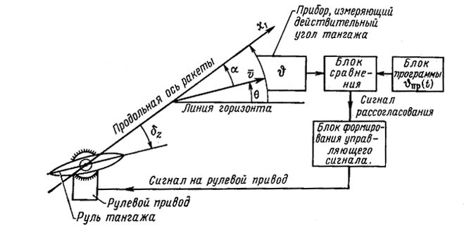
Figure 2. AD pitch control diagram#
During operation, the program block generates an electrical signal corresponding to the program pitch angle value at a given time ϑpr(t). At the same time, the sensing element measures the actual pitch angle ϑ and transmits the corresponding signal to the comparing unit, which, after comparing the signals proportional to the program and actual pitch angles, outputs a mismatch signal. Amplified and converted in the control signal generating unit, it is transmitted to a steering drive which rotates the controls accordingly. In this case, the direction of movement of the rocket will change so as to parry the resulting deviation from the program trajectory. Pitch mismatch angle can be approximately related to angle of rotation of control elements by means of first summand of control equation (5):
where \(k_{0ϑ}\) - static coefficient of the control system.
Hence (8), (9), (10) and (11):
For small angle of attack take (12):
As a result, the system of equations describing the longitudinal controlled flight of the AD is as follows (13), (14)и (15):
1. Properties#
Property |
Default Value |
Description |
Units of measurement |
|---|---|---|---|
Distance from the center of pressure of the controls to the center of mass of the AD |
0.45 |
- |
m |
AD surface area required to determine the moment Mz along Z axis |
0 |
- |
m\(^2\) |
Initial speed of AD |
55 |
- |
m/s |
Initial value of the trajectory inclination angle |
0 |
- |
rad |
X0 |
0 |
- |
- |
Y0 |
0 |
- |
- |
2. Inputs and outputs#
Parameters |
Input/Output |
Description |
Units of measurement |
Port type |
|---|---|---|---|---|
P |
Input |
Traction force vector in the related coordinate system |
N |
Automation |
X |
Input |
Frontal resistance of forces in the half-speed coordinate system |
N |
Automation |
Y_alpha (Y\(_\alpha\)) |
Input |
Lifting force in half-speed coordinate system |
N |
Automation |
Mz_alpha (M\(_{z \alpha}\)) |
Input |
Moment projection on the Z1 axis in the related coordinate system |
N\(\cdot\)m |
Automation |
Y\(_{p1}\) |
Input |
Sum of forces generated by controls in a related coordinate system |
N |
Automation |
m |
Input |
Mass |
kg |
Automation |
Q |
Input |
Velocity head |
N/\(m^2\) |
Automation |
Tang\(_{prog}\) |
Input |
Program angle value |
rad |
Automation |
K\(_{0tan}\) |
Input |
Control system factor |
- |
Automation |
\(v\) |
Output |
AD speed module |
m/s |
Automation |
theta (\(\theta\)) |
Output |
Flight-path angle |
rad |
Automation |
X\(_z\) |
Output |
Coordinates of longitudinal motion of the AD along the X axis |
m |
Automation |
Y\(_z\) |
Output |
Coordinates of longitudinal motion of the AD along the Y axis |
m |
Automation |
alpha (\(\alpha\)) |
Output |
Attack angle |
rad |
Automation |
In order to see the connection capabilities of the block, you need to go to page Description of block ports