

Full Movement of AD#
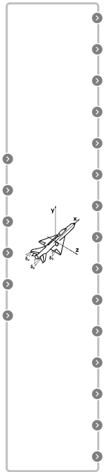
Block appearance in REPEAT VISION#
The movement of missiles will be considered in 0XeYeZe coordinate system rigidly connected to the Earth. Moreover, to simplify the task, the influence of the Earth will be taken into account by the introduction of a constant acceleration in magnitude and direction based on gravity, neglecting Coriolis acceleration; the curvature of the Earth will also not be taken into account. When writing the right-hand sides of the equations, the components of the thrust force, gravity, aerodynamic and control forces will be taken into account.
A system of equations describing the motion of the rocket center of mass in the half-speed coordinate system 0XYZ (1):
where:
\(P_x, P_{y^*}, P_{z^*}\) are projections of thrust force on half-speed coordinate axes;
\(Q_x, Q_{y^*}\) are projections of gravity on half-speed coordinate axes;
\(X_p, Y_{p^*}, Z_{p^*}\) is a projection of aerodynamic control forces on half-speed coordinate axes;
\(X, Y^*, Z^*\) is a projection of aerodynamic forces on half-speed coordinate axes.
The equations of rotational motion of rockets and aircraft are usually written in projections on the associated coordinate axes (2), (3) и (4):
where:
\(\sum M_{x_1}, \sum M_{y_1}, \sum M_{z_1}\) is the sum of the projections of the moments of external forces and thrust force to the associated coordinate axes (excluding control forces);
\(\sum M_{px_1}, \sum M_{py_1}, \sum M_{pz_1}\) are the sums of the projections of control forces moments on the associated coordinate axes;
\(J_{x_1}, J_{y_1}, J_{z_1}\) are the moments of inertia along the main axes of AD.
To establish links between velocity derivative and angular rate \(w_{x_1}, w_{y_1}, w_{z_1}\), use (5):
When determining the values of aerodynamic forces in the process of solving the spatial problem of missile motion, it is necessary to know the values of α, β and \(γ_s\) angles.
By defining the directional cosines of the sequential transition from the related axes to the wind axes, from the wind axes to the half-speed axes and from the half-speed axes to the earth’s axes and equating them to the directional cosines of the direct transition from the related axes to the earth’s axes, the following relations are obtained between (6), (7) and (8) angles:
Hence (9):
If expressions for projections of the velocity vector of the rocket center of mass on the axis of the Earth’s coordinate system are used, (10), (11) and (12) are obtained:
1. Properties#
Property |
Default Value |
Description |
Units of measurement |
|---|---|---|---|
Initial angular speed relative to the connected axis X1 \(\omega_{X0}\) |
0 |
- |
rad/s |
Initial angular speed relative to the connected axis Y1 \(\omega_{Y0}\) |
0 |
- |
rad/s |
Initial angular speed relative to the connected axis Z1 \(\omega_{Z0}\) |
0 |
- |
rad/s |
Initial speed \(v_0\) |
200 |
- |
m/s |
Initial angle of trajectory inclination \( heta_0\) |
0 |
- |
rad |
Initial angle of trajectory rotation \(\Psi_0\) |
0 |
- |
rad |
Initial yaw angle \(\psi_0\) |
0 |
- |
rad |
Initial pitch angle tang0 |
0 |
- |
rad |
Initial roll angle \(\gamma_0\) |
0 |
- |
rad |
Initial coordinate X\(_0\) |
0 |
- |
m |
Initial coordinate Y\(_0\) |
3000 |
- |
m |
Initial coordinate Z\(_0\) |
0 |
- |
m |
2. Inputs and outputs#
Parameters |
Input/Output |
Description |
Units of measurement |
Port type |
|---|---|---|---|---|
{Px,Py,Pz} |
Input |
Engine thrust vector in the half-speed coordinate system |
N |
Automation |
{Rx,Ry,Rz} |
Input |
Vector of aerodynamic forces in half-speed coordinate system |
N |
Automation |
g |
Input |
- |
m/s\(^2\) |
Automation |
mass |
Input |
- |
kg |
Automation |
{Ix,Iy,Iz} |
Input |
AD inertia moments |
kg\(\cdot m^2\) |
Automation |
{Mx,My,Mz} |
Input |
Vector of aerodynamic moments in a related coordinate system |
N\(\cdot\)m |
Automation |
Velocity |
Output |
AD speed module |
m/s |
Automation |
theta (\(\theta\)) |
Output |
Flight-path angle |
rad |
Automation |
omegaX (\(\omega_X\)) |
Output |
Angular velocity in the X axis |
rad/s |
Automation |
omegaY (\(\omega_Y\)) |
Output |
Angular velocity in the Y axis |
rad/s |
Automation |
omegaZ (\(\omega_Z\)) |
Output |
Angular velocity in the Z axis |
rad/s |
Automation |
PSI (\(\Psi\)) |
Output |
Trajectory rotation angle |
rad |
Automation |
psi (\(\psi\)) |
Output |
Yaw angle |
rad |
Automation |
tang (\(\upsilon\)) |
Output |
Pitch angle |
rad |
Automation |
gamma (\(\gamma\)) |
Output |
Roll angle |
rad |
Automation |
alpha (\(\alpha\)) |
Output |
Attack angle |
rad |
Automation |
beta (\(\beta\)) |
Output |
Gliding angle |
rad |
Automation |
gammaC (\(\gamma_C\)) |
Output |
Roll angle (angle between planes 0X1Y1 and 0XY*) |
rad |
Automation |
X |
Output |
Coordinate on X axis of earth coordinate system |
m |
Automation |
Y |
Output |
Coordinate on Y axis of earth coordinate system |
m |
Automation |
Z |
Output |
Coordinate on Z axis of earth coordinate system |
m |
Automation |
In order to see the connection capabilities of the block, you need to go to page Description of block ports