

Park transform (abc-dq0)#
Block appearance in REPEAT VISION#
The Park transform (abc-dq0) block performs a direct or reverse Park Transform. The block has a choice between the standard and power invariant transformation, the type of location of axis d relative to the axis of phase A.
Direct Park Transform allows switching from abc three-phase coordinate system to dq0 two-phase system rotating at rotor speed with a zero component.
Note
This component will be 0 for a symmetric system.
Reverse Park Transform allows the reverse transition: from dq0 two-phase coordinate system to abc three-phase coordinate system [1].
Note
The transformation type is determined by the selected value of property Transform direction.
Direct transformation is performed by the formula (1), reverse - by the formula (2):
where:
A, B, C – components of the three-phase coordinate system abc;
d, q, 0 – components of dq0 two-phase coordinate system;
\(\omega t \) – angle that determines the position of dq0 coordinate system at time moment t when moving at an angular speed \(\omega\);
\(\Theta _{dq}\) – angle between axes А and d.
The value \(\omega \)t is an input parameter for the block and is user-defined.
The value \(\Theta _{dq}\) is set in the block in the property
d axis position at the initial time. Depending on the selected value, axis d at the initial moment of time can be aligned with axis of phase A (see Fig. 1, a below), lag behind it by 90⁰ (see Fig. 1, b below) or can be shifted by an arbitrary angle relative to the axis of phase A (see Fig. 1, c below) in the range from -180⁰ to 180⁰ .
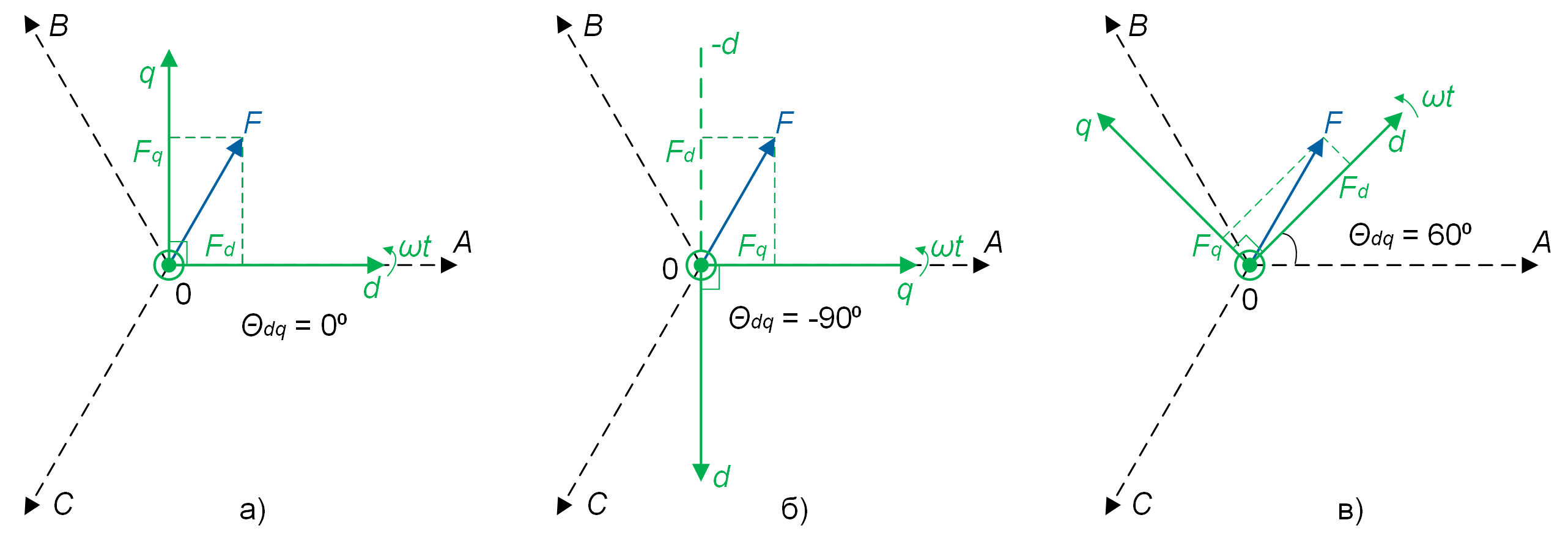
Fig. 1 Location of axes of coordinate systems at different values of the angle \(\Theta _{dq}\) at the initial moment of time#
Fig. 1 shows vector F - a generalized or depicting vector of a three-phase system rotating at a speed of \(\omega t \).
Expressions given in formulas (1) and (2) are standard Park Transform. However, if we calculate the active and reactive powers of the motor using these transformations, they will not coincide with similar values in the three-phase calculation system. In order to preserve the power values after the transformation, the Park transformation, invariant in power, is used, which is calculated using the formulas (3) and (4) [2]
Note
One can select this transformation type in the property Transform type.
1. Properties#
Property |
Default Value |
Description |
Units of measurement |
|---|---|---|---|
Transform direction: |
Direct |
- |
- |
Transform type: |
Standard |
- |
- |
d axis position at the initial time: |
Aligned with A axis |
- |
- |
45 |
- |
deg |
Note
Property becomes available when selecting the Other value in the property d axis position at the initial time
2. Inputs and outputs#
Note
The name of some input and output parameters depends on the value of the property Transform direction
Parameters |
Input/Output |
Description |
Units of measurement |
Port type |
|---|---|---|---|---|
A (“Direct”) / |
Input |
- |
- |
Automation |
B (“Direct”) / |
Input |
- |
- |
Automation |
C (“Direct”) / |
Input |
- |
- |
Automation |
\(\omega\) t |
Input |
- |
rad |
Automation |
d (“Direct”) / |
Output |
- |
- |
Automation |
q (“Direct”) / |
Output |
- |
- |
Automation |
0 (“Direct”) / |
Output |
- |
- |
Automation |
In order to see the connection capabilities of the block, you need to go to page Description of block ports
3. Code generation#
Important
Block supports C source code generation