

Jet pump (IH)#
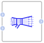
Block appearance in REPEAT VISION#
The Jet pump (IH) block models a liquid-to-liquid pump with an additional inlet for the suction liquid in an isothermal liquid network.
Description of pump operation
The block has three hydraulic ports:
main input port A;
suction inlet port S;
output port B.
The main fluid flow moves from port A to port B, accelerating in the converging nozzle. After the nozzle, in the low-pressure region, additional fluid is drawn in through port S. The mixing of flows occurs in a neck (mixing chamber) of constant cross-section, after which the liquid enters the diffuser, at the outlet of which its pressure increases as the flow expands.
Block properties
The
Nozzle areaproperty specifies the narrowest cross-section of the main flow (from port A to port B) immediately before mixing.The
Nozzle to throat area ratioproperty allows you to calculate the cross-section in the throat where the flows mix.The
Inlet to outlet diffuser area ratioproperty allows you to calculate the flow cross-section at the diffuser outlet, assuming that at the inlet it is equal to the throat cross-section calculated above.Properties:
allow you to set losses in the main and secondary inlets of the pump, as well as in the throat and diffuser.
The
Minimum nozzle pressureproperty allows you to limit the pressure at the point where it is minimal along the path of fluid from inlet A to outlet B of the pump.
Changes in pressure due to changes in area
The mass flow is stored in the pump (1) :
where:
\(M_a\) — mass flow through port A, [kg/s];
\(M_b\) — mass flow through port B, [kg/s];
\(M_s\) — mass flow through port S, [kg/s].
Using the law of conservation of mass and Bernoulli’s principle, we can express changes in area across pump segments in terms of pressure changes. The pressure change associated with the nozzle is:
(2) :
or 0, whichever is greater.
Here:
\(A_N\) — value of the parameter nozzle outlet cross-section area, [m\(^2\)];
\( ho\) is the density of the liquid, [kg/m\(^3\)].
The change in pressure due to the area at the suction opening is:
(3) :
or 0, whichever is greater.
Here \(A_T\) is the cross-sectional area of the throat (mixing chamber), [m\(^2\)].
The change in pressure during expansion of the diffuser is (4) :
where \(a\) is the value of the parameter of the ratio of the inlet area to the outlet area of the diffuser.
Pressure changes due to mixing
The driving and suction flows mix in the throat. The pressure change from mixing is equal to (5):
where b is the value of the parameter of the ratio of the area of the nozzle outlet cross-section to the area of the throat, which is determined between the largest and smallest cross-sectional areas of the nozzle.
Pressure losses due to friction
The flow loses pressure due to friction in the nozzle, secondary suction, throat, and diffuser. The unit calculates these losses based on a coefficient for each section and the area or area ratio between the different pump sections. Friction causes pressure loss regardless of flow direction. The pressure loss in the nozzle due to friction is (6) :
where \(K_N\) is the value of the loss coefficient parameter of the primary flow nozzle.
The pressure loss due to friction in the suction flow through the annular space is (7) :
where \(K_S\) is the value of the loss coefficient parameter at the input of the secondary flow.
The pressure loss in the throat due to friction is (8) :
where \(K_T\) is the value of the loss coefficient parameter in the neck.
The pressure loss in the diffuser due to friction is (9) :
where \(K_D\) is the value of the diffuser loss coefficient parameter. Since the block determines losses for areas of highest flow velocity, the block uses the throat area, which is equal to the diffuser inlet area, in the diffuser loss equation.
Saturation pressure in the nozzle
To avoid cavitation in the nozzle (the nozzle outlet is the point of lowest pressure in the pump), you can specify a minimum pressure in the nozzle.
Between the nozzle and the diffuser the pressure change is:
or (10) :
or \(P_B-P_{Nmin}\) - whichever is smaller.
The total change in pressure in the nozzle is (11) :
The total change in pressure in the annular space is (12) :
1. Properties#
Property |
Default Value |
Description |
Units of measurement |
|---|---|---|---|
0.01 |
- |
m\(^2\) |
|
0.25 |
- |
- |
|
0.25 |
- |
- |
|
0.05 |
- |
- |
|
0.005 |
- |
- |
|
0.1 |
- |
- |
|
0.1 |
- |
- |
|
0.1 |
- |
Pa |
2. Inputs and outputs#
Parameters |
Input/Output |
Description |
Units of measurement |
Port type |
|---|---|---|---|---|
Inlet A (primary line) |
Input |
- |
- |
Isothermal hydraulics |
Inlet S (suction line) |
Input |
- |
- |
Isothermal hydraulics |
Output |
Output |
- |
- |
Isothermal hydraulics |
In order to see the connection capabilities of the block, you need to go to page Description of block ports