

Torque converter#
Block appearance in REPEAT VISION#
The block models a hydrodynamic torque converter (see Fig. 1 below) consisting of a pump wheel, a turbine wheel and a stator (reactor). The turbine and pump wheels form a fluid coupling, and the stator increases torque by redirecting fluid flow back to the pump wheel. When the shaft turns the impeller, the fluid is pushed towards the turbine, causing it to rotate. The block is used to connect the engine to the automatic transmission: the Impeller port is connected to the engine, the Turbine port is connected to the transmission.
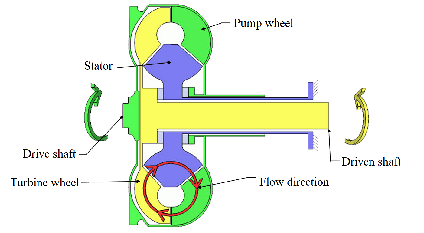
Fig. 1 Composition of the hydrodynamic converter#
Note
The unit operates in thrust mode, where power is directed from the pump wheel to the turbine wheel. The reverse power flow is modeled as a coastdown mode;
The unit uses the bandwidth factor to calculate torque based on angular velocity.
The transient mode of operation can be modeled either in a two-mode or continuous manner.
1. Two-Mode Transitional Mode#
When the Two-mode option is selected for the Coast mode modeling, the block calculates the moments separately for each mode (thrust and coast) (see Fig. 2 below). The block calculates torque relative to angular velocity using the expression (1) :
where:
\(K^*(R_{\omega})\) - the throughput coefficient, depending on the angular velocity ratio \(R_{\omega}\);
\(\omega\) - angular speed of the pump \(\omega_I\) or turbine wheel \(\omega_T\), [rpm].
Note
The capacity coefficient in the dual-mode mode is given in the dimension [\(\frac{N \cdot m}{(\frac{rev}{min})^2}\)]
Table 1
Mode |
Speed ratio |
Torque |
|---|---|---|
Traction |
\(R_{\omega}=\frac{\omega_T}{\omega_I}\) |
\(\tau_I=K^*_{drive}(R_{\omega}) \cdot \omega^2_I\) |
Coasting |
R̂\(_{\omega}=\frac{\omega_I}{\omega_T}\) |
\(\tau_T\)=K̂\(^*_{coast}\)(R̂\(_{\omega}\)) \(\cdot\) \(\omega^2_T\) |
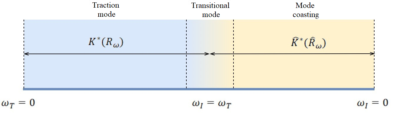
Fig. 2 Two-mode transient mode#
The Mode transition threshold parameter determines the speed of mode switching.
The torque transmission ratio variable \(R_{\tau}\) is a function of the angular velocity ratio \(R_{\tau}(R_{\omega})\) and amplifies the transmitted torque only in the traction mode; in the coasting mode, the torque transmission ratio is usually \(R_{\tau}\leq1\).
2. Continuous Transient Regime#
When the Coast mode modeling parameter is set to Continuous, the unit switches smoothly between thrust mode and coast mode. It is also possible to take into account the dynamics of the delay in torque transmission between the pump and turbine wheels. The model becomes less accurate when operating near the transient regime.
The block defines the ratio of velocities as \(R_{\omega}=\frac{\omega_T}{\omega_I}\) and the ratio of moments as \(R_{\tau}=\frac{\tau_T}{\tau_I}\).
Note
The continuous flow coefficient \(K^*\) is given in the dimension [\(\frac{N \cdot m}{(\frac{rad}{s})^2}\)]
The main expression for determining the torque of the pump wheel in continuous mode (2):
where \(\omega_I\) is the angular velocity of the pump wheel in [rad/s].
To take into account the torque transfer delay, you need to select the option Specify time constant and initial value in the Transmission lag model parameter. Then, in the calculations of the continuous mode model, the time constant \(t_c\) is added when calculating the torque \(\tau_I\) (3):
The main expression connecting the moments of the pump and turbine wheels (4) :
Limitations in continuous operation mode:
The impeller shaft must always rotate in the positive direction \(\omega_I>0\);
If you connect a torque converter to a torque source (e.g. ICE) you need to connect the moment of inertia to the torque source.
Hint
It is recommended that the impeller shaft have a positive initial angular velocity for calculation stability.
3. Interpolation and extrapolation of vector data#
The block uses vectors to determine the transmission coefficient \(K^*\) and the ratio of transmission moments \(R_{\tau}\).
The Interpolation method parameter allows you to select the interpolation method between points – Linear, Smooth.
The Extrapolation method parameter allows you to select the extrapolation method – Linear or Nearest. The selected method extrapolates the transmission coefficient and torque ratio functions.
Important
The torque ratio cannot be less than zero \(R_{\tau}>0\)
4. Properties#
Property |
Default Value |
Description |
Units of measurement |
|---|---|---|---|
Coast mode modeling: |
Two-mode |
- |
- |
Speed ratio vector |
0.0;0.5;0.6;0.7;0.8;0.87;0.92;0.94;0.96;0.97;1.0 |
Available, when |
- |
Capacity factor vector |
0.006616;0.006048;0.005787;0.005384;0.004681; |
Available, when |
N\(\cdot\)m/\((rad/s)^2\) |
Torque ratio vector |
2.232;1.5462;1.4058;1.2746;1.1528;1.0732; |
Available, when |
- |
Transmission lag model: |
No lag |
Available, when |
- |
Torque transmission time constant |
0.05 |
Available, when |
s |
Initial turbine-to-impeller torque ratio |
0.0 |
Available, when |
- |
Drive mode speed ratio vector |
0.0;0.5;0.6;0.7;0.8;0.87;0.92;0.94;0.96;0.97;1.0 |
Available, when |
- |
Drive mode capacity factor vector |
7.2558E-5;6.6322E-5;6.3463E-5;5.9042E-5; |
- |
N\(\cdot\)m/\((rpm)^2\) |
Drive mode torque ratio vector |
2.232;1.5462;1.4058;1.2746;1.1528; |
- |
- |
Coast mode speed ratio vector |
0.0;0.5;0.6;0.7;0.8;0.87; |
- |
- |
Coast mode capacity factor vector |
5.079E-5;4.643E-5;4.442E-5;4.133E-5;3.593E-5; |
- |
N\(\cdot\)m/\((rpm)^2\) |
0.2 |
- |
rad/s |
|
Interpolation method: |
Linear |
- |
- |
Extrapolation method: |
Linear |
- |
- |
5. Inputs and outputs#
Parameters |
Input/Output |
Description |
Units of measurement |
Port type |
|---|---|---|---|---|
Input |
- |
- |
Rotational motion |
|
Output |
- |
- |
Rotational motion |
In order to see the connection capabilities of the block, you need to go to page Description of block ports