

Symmetric components#
Block appearance in REPEAT VISION#
The Symmetric components block calculates the parameters of symmetric components (direct, reverse, zero sequences) or parameters of a three-phase asymmetric system depending on the value of the property Transform type.
It is necessary to supply three phase values sinusoidal signals to the block input when selecting the
Directvalue for the propertyTransform type. The result of the calculation will be the amplitudes and phases of components of the direct, reverse and zero sequences for phase A. In this case, one can select the parameters of which sequence one wants to calculate in the block in the propertyCalculatable sequence.
Note
Since this type of transformation performs Fourier analysis of input signals, it is necessary to additionally set the base frequency and harmonic number. The initial amplitude and phase values set in the block will be used to calculate symmetric components during the first base frequency period.
It is necessary to supply the amplitudes and phases of the direct, reverse and zero sequences of phase A when selecting the
Reversevalue for the propertyTransform type. The calculation results will be the amplitudes and phases of the original three-phase system. In this case one can select which phase parameters should be calculated in the block in the propertyCalculatable phase.
Calculation of symmetric components is implemented in accordance with the formula (1) [1], calculation of phase quantities - with the formula (2) [1].
where:
\(a=e^{j\cdot \frac{2\cdot \pi}{3}}=-0.5+j\cdot \frac{\sqrt{3}}{2}\) – three-phase system operator [1];
А, В, С – initial asymmetric system of three currents / voltages of the same frequency;
A\(_1\), A\(_2\), A\(_0\) – vectors of the direct, reverse and zero sequences of phase A.
If necessary, it is possible to calculate similar parameters for phases B (3) and С (4) using \(a\) three-phase system operator from the parameters of symmetric components of phase A obtained by the formula (1):
A graphic representation of the symmetric component method for the case of a two-phase ground fault is shown in Fig. 1:
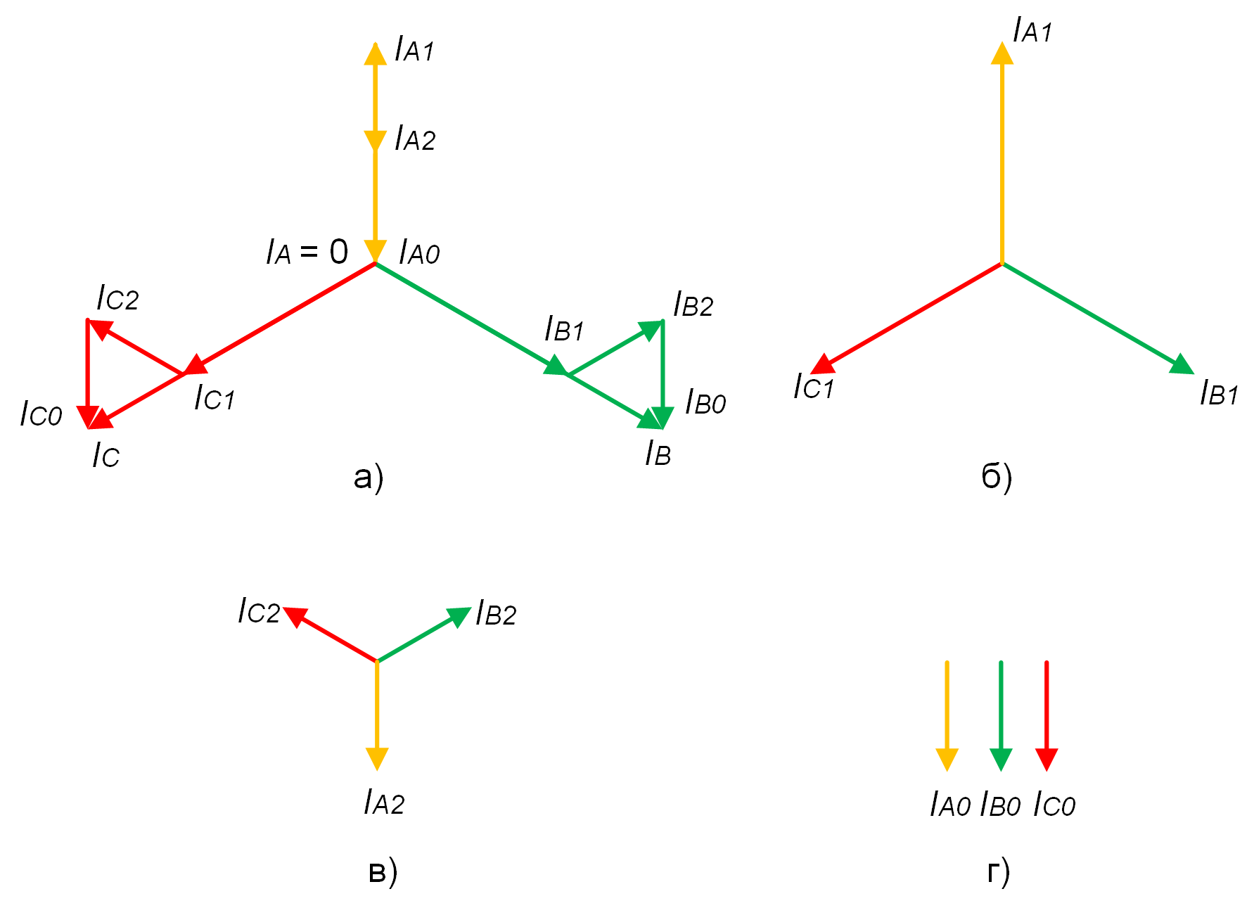
Fig. 1 Current decomposition by the method of symmetric components at two-phase SC to ground: a) phase current vectors; b) direct sequence; c) reverse sequence; d) zero sequence#
1. Properties#
Property |
Default Value |
Description |
Units of measurement |
|---|---|---|---|
Transform type: |
Direct |
- |
- |
Fundamental frequency, available when selecting |
50 |
- |
Hz |
Harmonic number, available when selecting |
1 |
- |
- |
Initial signal amplitude value, available when selecting |
0 |
This value will be the same for three phases during the first base frequency period |
- |
Initial signal phase value, available when selecting |
0 |
Value is set for phase A. During the first base frequency period, the three-phase value system is assumed to be symmetric |
degr |
Calculatable sequence: |
Direct |
- |
- |
Calculatable phase: |
Phase A |
- |
- |
Sampling type: |
Decimation factor of project fundamental discretization frequency |
- |
- |
Sample time, available when selecting |
0.05 |
- |
s |
Decimation factor of project fundamental discretization frequency, available when selecting |
1 |
- |
- |
Sampling frequency, available when selecting |
20 |
- |
Hz |
2. Inputs and outputs#
Note
The block has a variable number of input and output ports depending on the value of the Transform type and Calculatable sequence / Calculatable phase properties:
Parameters |
Input/Output |
Description |
Units of measurement |
Port type |
|---|---|---|---|---|
A |
Input |
Available when selecting |
- |
Automation |
B |
Input |
Available when selecting |
- |
Automation |
C |
Input |
Available when selecting |
- |
Automation |
Amplitude \(A_1\) |
Input |
Available when selecting |
- |
Automation |
Phase \(A_1\) |
Input |
Available when selecting |
degr |
Automation |
Amplitude \(A_2\) |
Input |
Available when selecting |
- |
Automation |
Phase \(A_2\) |
Input |
Available when selecting |
degr |
Automation |
Amplitude \(A_0\) |
Input |
Available when selecting |
- |
Automation |
Phase \(A_0\) |
Input |
Available when selecting |
degr |
Automation |
Amplitude |
Output |
Available when selecting |
- |
Automation |
Phase |
Output |
Available when selecting |
degr |
Automation |
Output signal 1 (amplitude) |
Output |
Available when selecting |
- |
Automation |
Output signal 1 (phase) |
Output |
Available when selecting |
degr |
Automation |
Output signal 2 (amplitude) |
Output |
Available when selecting |
- |
Automation |
Output signal 2 (phase) |
Output |
Available when selecting |
degr |
Automation |
Output signal 3 (amplitude) |
Output |
Available when selecting |
- |
Automation |
Output signal 3 (phase) |
Output |
Available when selecting |
degr |
Automation |
In order to see the connection capabilities of the block, you need to go to page Description of block ports