

Single-phase transmission line#
Block appearance in REPEAT VISION#
In the Single-phase transmission line block, a mathematical model of a single-phase line, represented by U-shaped equivalent circuit, is shown in Fig. 1:
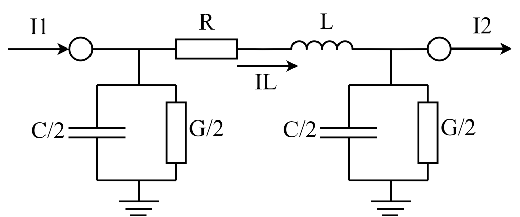
Fig. 1 Single phase line represented by U-shaped equivalent circuit#
The model takes into account the following physical phenomena accompanying the power line operation:
Conductor heating. It is taken into account by active resistance R, [Ohm];
Conductor self-induction. It is taken into account by inductance L, [H];
Electrostatic field between line and ground. It is taken into account by tanks S/2, [F], to earth at both ends of the line;
Corona. It is taken into account by active conductivities G/2, [S], to earth at both ends of the line.
The block implements three scenarios to set model parameters. Their description is given in the table.
1. Three scenarios to set model parameters#
Description |
|
|---|---|
RLCG |
The user sets the value of the active resistance R, inductance L and capacity C manually. It is necessary to put a tick in the corresponding field to set the conductivity value G. It is important to note that capacity and conductance are at both ends of the model, so that their values at each end are half of the given values. |
Linear parameters |
The user sets the length of the line l, km, and the values of its linear parameters: linear active resistance \(r_0\), Ohm/km, \(l_0\), Hn/km, \(s_0\), F/km and \(g_0\), S/km. Model parameters are thus defined as: \(R=r_0\cdot l; L=l_0\cdot l; C=c_0\cdot l; G=g_0\cdot l \) It is necessary to put a tick in the corresponding field to set the value of the conductivity \(g_0\). |
Linear parameters taking into account hyperbolic adjustments |
When choosing this option, the user sets the frequency f, Hz, to calculate the correction factors, the line length l, km, and the values of its linear parameters: linear resistance \( r _ 0 \), Ohm/km, \( l _ 0 \), H/km, \( c _ 0 \), F/km and \( g _ 0 \), S/km model parameters are calculated as follows: The value of the base angular frequency is determined, rad/s: \(\omega =2\cdot \pi \cdot f; \) The value of the linear impedance is determined: \(z=r_0+j\cdot \omega \cdot l_0; \) The total conductivity is determined (depending on whether conductivity is included, this value will have an active component or not): \(y=g_0 +j\cdot \omega \cdot c_0;\) The characteristic impedance value is determined: \(Z_c=\sqrt {\frac {z}{y}};\) The value of spreading constant is determined: \( \gamma = \sqrt {z\cdot y}\) Then values of active resistance R, Ohm, inductance L, Hn, capacity C, F and conductivity G, Cm, lines if the corresponding tick is set: \(Z=Z_c\cdot sinh(\gamma \cdot l); R=real(Z); L=\frac{imag(Z)}{\omega}; Y=\frac{2}{Z_c}\cdot tanh(\gamma \cdot l/2); C=\frac{imag(Y)}{\omega}; G=real(Y)\)| |
2. Properties#
Property |
Default Value |
Description |
Units of measurement |
|---|---|---|---|
Method of setting model parameters: |
Linear parameters taking into account hyperbolic adjustments |
– |
– |
Off |
– |
– |
|
Active resistance |
10 |
Available, when |
Ohm |
Inductance |
1.e-3 |
Available, when |
H |
Ground capacitance |
1.e-6 |
Available, when |
F |
Ground conductance |
1.e-6 |
Available, when |
S |
Line length |
100 |
Available, when |
km |
Base frequency |
50 |
Available, when |
Hz |
Per-unit length resistance |
1.e-3 |
Available, when |
Ohm/km |
Per-unit length inductance |
1.e-3 |
Available, when |
H/km |
Per-unit length capacitance |
1.e-6 |
Available, when |
F/km |
Per-unit length conductance |
1.e-6 |
Available, when |
S/km |
3. Inputs and outputs#
Parameters |
Input/Output |
Description |
Units of measurement |
Port Type |
|---|---|---|---|---|
+ |
Input |
- |
- |
Electronics |
- |
Output |
- |
- |
Electronics |
In order to see the connection capabilities of the block, you need to go to page Description of block ports
See also
An example of using this block can be found in subsection Power industry of section Electrical equipment practical guide Modeling of zero-sequence current directional protection of 220 kV power transmission lines.