

Plate Heat Exchanger (TL-TL)#
Block appearance in REPEAT VISION#
Block simulates a plate heat exchanger in which heat exchange occurs between two thermohydraulic systems.
Heat flow is calculated using NTU method. User can add accounting of plates thermal resistance and deposits on their surfaces.
The coolant movement (counterflow)[1] in the heat exchanger is shown in Fig. 1.
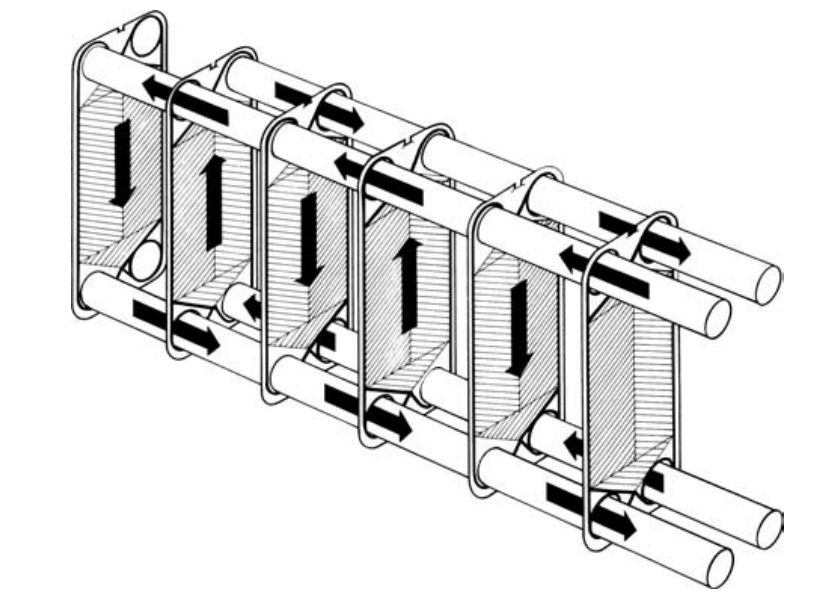
Fig. 1 General view of coolant movement in the heat exchanger (counterflow)#
The geometry of plate corrugation[4] is shown in Fig. 2.
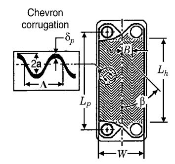
Fig. 2 - Corrugation geometry of plates
φ - corrugation angle;
2\(a\) is a distance between plates;
Λ - corrugation pitch;
L\(_h\) is a plate length;
W is a plate width.#
Total volume of medium in heat exchanger (1) :
where:
\(n_{pl}\) – number of plates in the heat exchanger excluding extreme ones, [pcs];
b – distance between plates, [m];
\(L_{pl}\) – length of plates, [m];
\(W_{pl}\) – width of plates, [m].
Volume of one medium in the heat exchanger {eq} PlateHeatExchangerTH2 :
Cross-sectional area for one medium (3) :
Total heat exchange surface area excluding plate corrugation (4) :
The heat exchange surface area for one medium is half of the total heat exchange surface without corrugation multiplied by the area increase factor for corrugation (5) :
where \(\phi\) is coefficient of increase of plate surface area.
Coefficient \(\phi\) is the ratio of actual surface area to surface area excluding corrugation (6) :
where \(А_{actual}\) is the actual heat exchange surface area.
In the block, the plate surface area increase factor can be set by the user or calculated using the following formula based on the specified corrugation geometry (if Corrugation geometry is selected as Specification of corrugation pattern)[2] (7) :
where \(\lambda\) is corrugation pitch, [m].
Hydraulic diameter (8) :
1. Heat Exchange#
NTU convective heat exchange (9) :
where:
\(\epsilon\) – heat exchanger efficiency factor;
\(C_{min}\) – minimum values of \(\dot m_1 \cdot C_{p1}\) and \(\dot m_2 \cdot C_{p2}\), [\(\frac{W}{℃}\)];
\(\dot m_1, \dot m_2\) – mass flow rate of medium 1 and 2, [\(\frac{kg}{s}\)];
\(C_{p1}, C_{p2}\)– specific heat capacity of medium 1 and 2, [\(\frac{J}{kg\cdot ℃}\)];
\(T_{in}^{aver1}, T_{in}^{aver2}\) – medium 1 and 2 temperature at heat exchanger input, [℃].
Heat exchanger efficiency (10):
where:
Q - actual heat flux, [W];
Q\(_{max}\) is maximum possible heat flow, [W].
Formula for calculating heat exchanger efficiency for different mutual motion of coolant [3]:
Sump (11) :
where:
NTU - number of heat transfer units;
\(C_{rel}=\frac{C_{min}}{C_{max}}\).
Counterflow (12) :
For \(C_{rel}\)=1 (13) :
Number of heat transfer units (14) :
where \(R_{conv}\) is the total thermal resistance between two liquids without taking into account the thermal conductivity of the liquids, [\(\frac{℃}{W}\)] (15) :
where:
emsp;\(\alpha_1, \alpha_2\) - heat transfer coefficients for media 1 and 2, [\(\frac{W}{m^2 \cdot℃}]\);
\(A_{aver1}, A_{aver2}\) – heat transfer surface area for medium 1 and 2, [m\(^2\)];
\(R_{f1}, R_{f2}\) are surface contamination coefficients for media 1 and 2, [\(\frac{m^2 \cdot℃}{W}\)];
\(R_{pl}=\frac{t}{\lambda_{pl}\cdot n_{pl}\cdot L_{pl}\cdot W_{pl}}\) – plate thermal resistance, [\(\frac{℃}{W}\)];
\(\lambda_{pl}\) – plate thermal conductivity, [\(\frac{W}{m^2 \cdot℃}\)];
t - plate thickness, [m].
Heat transfer coefficient (16) :
where:
\(\lambda\) – medium thermal conductivity, [\(\frac{W}{m^2 \cdot℃}\)];
Nu is the Nusselt number.
If Calculation type for the heat transfer coefficient property is seected (17):
where:
a,b,c are coefficients set by the user;
Re=\(\frac{w \cdot d_г}{ u}\) – Reynolds number;
w – medium speed, [\(\frac{m}{s}\)];
& emsp; \( u \) - kinematic viscosity of medium, [\(\frac{m^2}{s}\)];
Pr is the Prandtl number.
If Calculation type for the heat transfer coefficient property is selected - Correlation for flow between corrugated plates (without taking into account the correction for the temperature dependence of the medium viscosity)[2] (18) :
where:
\(c_1, c_2, c_3\) – coefficients of dependence for flow between corrugated plates;
\(f\) - Darcy friction factor;
\(\beta\) - corrugation angle,°.
Thermal flux of thermal conductivity (19) :
where:
\(T^{aver1}_{out}, T^{aver2}_{out}\) – medium 1 and 2 temperature at the heat exchanger output, [℃];
\(R_{heat}\) – thermal resistance of thermal conductivity, \(\frac{℃}{W}\) (20):
where \(\lambda_1, \lambda_2\) are thermal conductivity coefficients for medium 1 and 2, [\(\frac{W}{m^2\cdot℃}\)].
The resulting heat flux between the coolants is the sum of the convective and conductive component (21) :
Pressure loss in the heat exchanger
The pressure loss between the block ports and the internal unit is calculated using the following formulas (22) :
where:
\(p^{aver}_{input}, r^{aver}_{output}, p^{aver}_{input}\) - medium pressure at input, output and in internal unit, respectively, [Pa];
\(\dot m_{input},\dot m_{output}\) – mass flow rate of medium at input and output of heat exchanger, [\(\frac{kg}{s}\)];
\(\xi\) – input and output pressure loss factor;
\( ho\) – medium density, [\(\frac{kg}{m^2}\)];
\(S_{input port}, S_{output port}\) – cross-sectional area of input and output port, [m\(^2\)].
If
Pressure loss calculation typeis selected -Constant Darcy friction factor, then the loss ratio is equal to the one set by the user.If
Pressure loss calculation typeis selected -Correlation for flow between corrugated plates, then the loss factor is calculated from the following formula [2]:For Re<2000 (23) :
(23)#\[\frac{1}{\sqrt{f}}=\frac{cos \beta}{\sqrt{0.18 \cdot tg \beta +0.36 \cdot sin \beta + \frac{64}{Re \cdot cos \beta}}}+\frac{1-cos \beta}{\sqrt{3.8 \cdot (\frac{597}{Re}+3.85)}}\]For Re\(\geq\) 2000 (24) :
(24)#\[\frac{1}{\sqrt{f}}=\frac{cos \beta}{\sqrt{0.18 \cdot tg \beta +0.36 \cdot sin \beta + \frac{1}{(1.8 \cdot lgRe - 1.5)^2 \cdot cos \beta}}}+\frac{1-cos \beta}{\sqrt{\frac{3.8\cdot 39}{Re^{0.289}} }}\]
Mass conservation equation (25):
where M – mass of medium, [kg].
Energy conservation equation (26):
where:
\(\phi^{aver}_{in}, \phi^{aver}_{out}\) – energy flow at input and output, [W];
Q – heat flux, [W];
h – enthalpy of medium in internal unit, [\(\frac {J}{kg}\)];
\(\alpha\) – coefficient of isobaric thermal expansion, \(\frac {1}{K}\);
\(\beta\) – volumetric modulus of elasticity, [Pa];
\(T_{in}\) – medium temperature in internal unit, [℃];
V – volume of medium in the heat exchanger, [m\(^3\)].
2. Properties#
Property |
Default Value |
Description |
Units of measurement |
|---|---|---|---|
Flow arrangement:<brCounter flow; |
Counter flow |
- |
- |
Number of plates |
27 |
- |
pieces |
Plate length |
1.2 |
- |
m |
Plate width |
0.6 |
- |
m |
Spacing between plates |
0.006 |
- |
m |
Specification of corrugation pattern: |
Surface area enlargement factor |
- |
- |
Surface area enlargement factor, available when selecting |
1.25 |
- |
- |
Corrugation angle, available when selecting |
60.0 |
- |
degrees |
Corrugation depth to pitch ratio, available when selecting |
0.28 |
- |
- |
выкл |
- |
- |
|
Plate thickness, available when selecting |
5.5E-4 |
- |
m |
Plate thermal conductivity, available when selecting |
13.0 |
- |
W/(m\(\cdot\)K) |
Inlet cross-sectional area (liquid 1) |
0.1 |
- |
m\(^2\) |
Inlet cross-sectional area (liquid 2) |
0.1 |
- |
m\(^2\) |
Outlet cross-sectional area (liquid 1) |
0.1 |
- |
m\(^2\) |
Outlet cross-sectional area (liquid 2) |
0.1 |
- |
m\(^2\) |
Pressure loss calculation type (liquid 1): |
Constant Darcy friction factor |
- |
- |
Darcy friction factor for corrugated plates (liquid 1), available when selecting |
1.8 |
- |
- |
Inlet and outlet loss coefficient (liquid 1) |
1.5 |
- |
- |
Calculation type for the heat transfer coefficient (liquid 1): |
Nu = \(\alpha \cdot Re^b \cdot Pr^c\) |
- |
- |
Coefficients for equation \(\alpha \cdot Re^b \cdot Pr^c\) (liquid 1), available when selecting |
0.141; 0.748; 0.333; |
- |
- |
Correlation coefficients for flow between corrugated plates (liquid 1), available when selecting |
0.122; 0.374; 0.333; |
- |
- |
Fouling factor (liquid 1) |
0.1 |
- |
K\(\cdot m^2\)/kW |
Initial liquid pressure (liquid 1) |
0.0 |
- |
MPa |
Initial liquid temperature (liquid 1) |
20.0 |
- |
℃ |
Pressure loss calculation type (liquid 2): |
Constant Darcy friction factor |
- |
- |
Darcy friction factor for corrugated plates (liquid 2), available when selecting |
1.8 |
- |
- |
Inlet and outlet loss coefficient (liquid 2) |
1.5 |
- |
- |
Calculation type for the heat transfer coefficient (liquid 2): |
Nu = \(\alpha \cdot Re^b \cdot Pr^c\) |
- |
- |
Coefficients for equation \(\alpha \cdot Re^b \cdot Pr^c\) (liquid 2), available when selecting |
0.141; 0.748; 0.333; |
- |
- |
Correlation coefficients for flow between corrugated plates (liquid 2), available when selecting |
0.122; 0.374; 0.333; |
- |
- |
Fouling factor (liquid 2) |
0.1 |
- |
K\(\cdot m^2\)/kW |
Initial liquid pressure (liquid 2) |
0.0 |
- |
MPa |
Initial liquid temperature (liquid 2) |
20.0 |
- |
℃ |
3. Inputs and outputs#
Parameters |
Input/Output |
Description |
Units of measurement |
Port type |
|---|---|---|---|---|
Liquid 1 inlet |
Input |
- |
- |
Thermohydraulics |
Liquid 2 inlet |
Input |
- |
- |
Thermohydraulics |
Liquid 1 outlet |
Output |
- |
- |
Thermohydraulics |
Liquid 2 outlet |
Output |
- |
- |
Thermohydraulics |
In order to see the connection capabilities of the block, you need to go to page Description of block ports
4. Examples of use#
Examples of using this block can be found in the following sections:
Tutorials;
Description of Demo.
How-to guides
Section |
Guide name |
|---|---|
Energy |
Development of a model of the industrial circuit system of oil coolers of NPP with WCWR |