

Spool Orifice (IH)#
Block appearance in REPEAT VISION#
The Spool Orifice (IH) block simulates changes in energy and pressure of the liquid when component of isothermal fluid system passes - holes of variable area between the coil and the sleeve with holes. The sleeve holes can be a series of circular or rectangular holes. The flow rate depends on the total area of hole between the sleeve, holes and the spool, which is extended or retracted depending on the signal received at port S.
The force acting on the coil is calculated as (1):
where:
\(\dot{m_A}\) - mass flow rate in port A, [kg/s];
\( ho\) – fluid density, [kg/m\(^3\)];
A — open area of the hole, which is determined by the spindle position and the parameterization of the hole, [m\(^2\)];
\(\epsilon\) - hole orientation, which indicates the hole’s hole that is associated with a positive or negative signal at point S.
\(\alpha\) - jet angle, which is calculated by approximation of von Mises formula (2):
where:
c - radial clearance;
h - height of the hole.
1. Hole area#
Set the Open orientation to Positive for adjustable holes indicates that the hole opens when the control is extended, and Negative indicates that the hole opens when the control is retracted.
Leakage area is considered to be a small area opened to flow when the hole is closed, which provides numerical continuity. In addition, the non-zero Smoothing factor can provide increased numerical stability when the hole is in an almost closed or almost opened position.
Round holes
Set Orifice parametrization to Round uniformly distribute a user-defined number of holes around the perimeter of the sleeve with identical diameters and centers located in the same plane, Fig. 1:
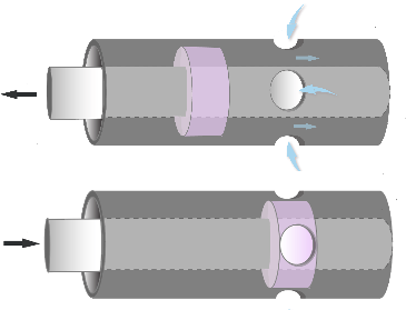
Fig. 1 Hole parameterization#
The open area is calculated as (3):
Opening angle of hole θ is set by control signal in (4):
where:
\(n_0\) - number of holes;
\(d_0\) - diameter of holes;
\(A_{leak}\) = c \(\cdot\) d\(_0\)\(\cdot\) n\(_0\)
\(\Delta S\) – distance of control movement from initial position.
The maximum open area is (5):
Rectangular hole
Setting Orifice parametrization - Rectangle for simulation of one rectangular slot in the pipe coupling, Fig. 2:
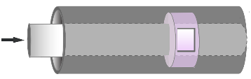
Fig. 2 Rectangular hole#
Open area for a hole with a slot in a rectangular sleeve is equal to (6):
where w — hole width.
The maximum opening distance between the sleeve and the casing is (7):
where \(\Delta S_{max}\) – distance between the slot hole and the distance between closed and opened hole.
The leakage area at the minimum hole area of the hole is (8):
2. Numerically smoothed displacement#
You can maintain numerical stability in your simulation by adjusting the block at extremes of the hole opening range Smoothing factor. The block applies a smoothing function to each calculated displacement, but primarily affects the simulation at extremes of this range.
If Smoothing factor is not zero, the block smoothly saturates the hole between 0 and \(\Delta S_{max}\), where \(\Delta S_{max}\):
Value for
Orifice diameterwhenOrifice parametrizationis set toRound.Parameter value
Spool travelwhenOrifice parametrizationset toRectangle.
3. Mass flow rate equation#
The mass is retained by the valve (9):
The mass flow rate through the valve is calculated as (10):
where:
\(C_d\) - discharge coefficient;
\(A_{orifice}\) - open area of the hole, except cases, when:
“Opening is greater or equal to the area
Spool traveldistance between holes. Then the opening area will be \(A_{max}\).Hole opening is less than or equal to minimum opening distance. Then the area of the hole is equal to the leakage.
\(A_{port}\) - Port area A and B;
\(\bar\rho\) - average fluid density;
\(\Delta p\) - pressure difference at valve \(p_A\) - \(p_B\).
The critical pressure drop \(\Delta p_{crit}\), is the pressure drop associated with Critical Reynolds number, Re\(_{crit}\), the transition point of the flow mode between laminar and turbulent flow (11):
The pressure loss describes a decrease in pressure in the valve due to a decrease in area. PR losses are calculated as (12):
Pressure recovery describes a positive pressure change in the valve due to area increase. If you do not want to record this pressure increase, remove Pressure recovery flag. In this case, \(PR_{loss}\) is 1.
4. Properties#
Property |
Default value |
Description |
Units of measurement |
|---|---|---|---|
Orifice parametrization: |
Round |
- |
- |
Open orientation: |
Positive |
- |
- |
Off |
- |
- |
|
1.0E-10 |
- |
m\(^2\) |
|
5e-3 |
Available, when |
m |
|
Orifice quantity |
6.0 |
Available, when |
pcs |
Rectangle width |
0.01 |
Available, when |
m |
0.005 |
Available, when |
m |
|
Spool offset |
0.0 |
- |
m |
0.07 |
- |
m\(^2\) |
|
Discharge coefficient |
0.64 |
Available, when |
- |
150.0 |
The Reynolds number at which the transition from laminar to turbulent flow occurs |
- |
|
0.01 |
- |
- |
5. Inputs and outputs#
Parameters |
Input/Output |
Description |
Units of measurement |
Port type |
|---|---|---|---|---|
Auto |
Input |
- |
m |
Automation |
Input |
Input |
- |
- |
Isothermal Hydraulics |
Output |
Output |
- |
- |
Isothermal Hydraulics |
In order to see the connection capabilities of the block, you need to go to page Description of block ports