

Compound planetary gear#
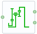
Block appearance in REPEAT VISION#
The Compound planetary gear block models a planetary gear transmission with composite planetary gears. Each composite planetary gear is a pair of rigidly connected gears of different radii located along a common axis. One of the two gears meshes with the central sun gear, and the other meshes with the outer ring gear.
This block is a structural component consisting of the blocks Sun-planet and Ring-planet Fig. 1:
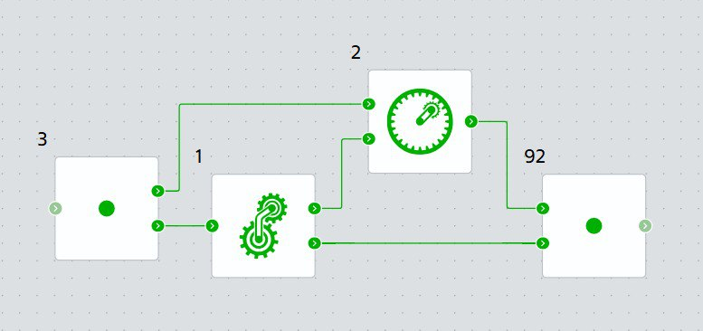
Fig. 1 Block components#
The model imposes two kinematic and two geometric constraints on the connected transmission shafts: CompoundPlanetaryGear :
\(r_{вод.} \cdot \omega_{вод.} = r_{сол.}\cdot \omega_{сол.} +r_{сат.1} \cdot \omega_{сат.}\\r_{корон.} \cdot ω_{корон.}= r_{вод.} \cdot ω_{вод.} + r_{сат.2}\cdot ω_{сат.}\\r_{вод.}= r_{сол.}+ r_{сат.1} \\r_{корон.}= r_{вод.} + r_{сат.2}\)$(CompoundPlanetaryGear)
where:
\(r_{car.}\) – distance from the transmission axis to the satellite axis (satellite installation radius);
\(\omega_{car.}\) – angular velocity of the carrier;
\(r_{crown.}\) – radius of the crown gear;
\(\omega_{crown.}\) – angular velocity of the crown gear;
\(r_{sun}\) – radius of the sun gear;
\(\omega_{sun}\) – angular velocity of the sun gear;
\(r_{sat.1}\) – radius of the first stage of the satellite;
\(r_{sat.2}\) – radius of the second stage of the satellite;
\(ω_{sat.}\) – angular velocity of the satellite.
The gear ratio between the ring gear and the second stage of the planetary gear (1) :
where:
\(g_{PS}\) – gear ratio between the sun gear and the first stage of the satellite;
\(g_{RP}\) – gear ratio between the ring gear and the second stage of the satellite;
\(N\) is the number of teeth of the corresponding gear.
Note
For the transmission to operate correctly, the gear ratio g_RP must be strictly greater than one.
The main kinematic constraint in terms of gear ratios relates the angular velocities of the shafts of the transmission (2):
The four degrees of freedom of the system are reduced to two independent degrees of freedom. The model uses two gear pairs: “second stage of satellites – crown gear” and “sun gear – first stage of satellites”, for which the transmission agreement (1,2) = (P2, crow.) and (sun, P1) is adopted.
The transmission of torque in the block is described by the equations:
for engagement solar – first stage of satellites (3) :
for engagement the second stage of the satellites is the crown gear (4) :
where:
\(M_{P2}\) – transmission moment for the second stage of satellites;
\(M_{crow.}\) – transmission moment for the crown gear;
\(M_{sun}\) – transmission moment for the sun gear;
\(M_{losses}\) – the moment of loss (equal to zero in the ideal case).
1. Properties#
Property |
Default Value |
Description |
Units of measurement |
|---|---|---|---|
Ring (R) to planet (P) teeth ratio (N_R/N_P) |
2.0 |
- |
- |
Planet (P) to sun (S) teeth ratio (N_P/N_S) |
1.0 |
- |
- |
2. Inputs and outputs#
Parameters |
Input/Output |
Description |
Units of measurement |
Port type |
|---|---|---|---|---|
Carrier (C) |
Input |
- |
- |
Rotational motion |
Ring (R) |
Output |
- |
- |
Rotational motion |
Sun (S) |
Output |
- |
- |
Rotational motion |
In order to see the connection capabilities of the block, you need to go to page Description of block ports