

PLL (3 phase)#
Block appearance in REPEAT VISION#
Block PLL (3 phase) implements the phase frequency autotuning loop (PLL) receiving a three-phase input signal.
The unit is based on the standard structure of the three-phase PLL [1]. Within the block, it is possible to select a phase difference generation method through Implementation of phase difference forming property, according to which the PLL structure will change. So, two options are possible:
Angle between d and q components. Their block diagrams are shown in Fig. 1 and 2 respectively.
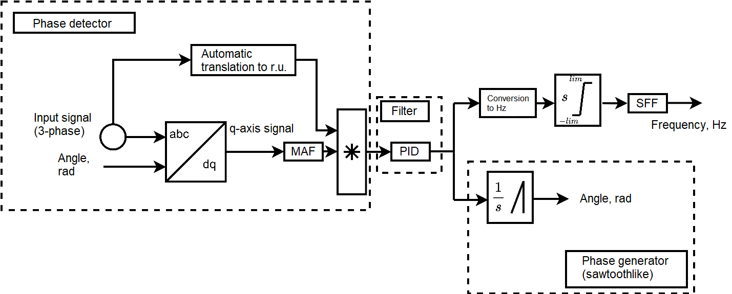
Fig. 1 Block diagram of three-phase PLL (q-axis component)#
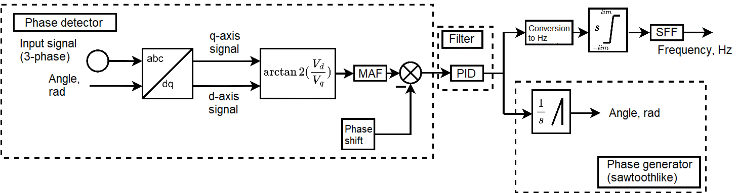
Fig. 2 Block diagram of three-phase PLL (Phase shift between dq-components)#
Note
This model is designed to calculate the frequency and phase of the input three-phase sinusoidal signal.
Model consists of the following functional parts:
Phase detector. Generates phase difference signal of input sinusoid and phase generator.
Important
In q axis component configuration, a signal in relative units is expected at the input, and in the Angle between d and q components configuration, this is irrelevant.
Also, the block implements the possibility of filtering the phase difference signal using the Moving Average Filter (MAF). It can be activated via Moving average filter
Important
In the configuration Angle between d and q components, the output signal of the Phase Detector is the difference between the calculated angle and the offset set point set in the property Angle offset between d and q.
Note
In the block, it is possible to implement automatic transfer of the signal from named units to relative ones by multiplying by a coefficient calculated from the input signal module. To enable such functionality, the block provides the property Adaptive gain. This functionality is not available for the Angle between d and q components block configuration, since it does not matter for the arctangent function whether the input signal is in named or relative units
Filter. It is a PID controller that generates a signal based on the phase difference determined by the phase detector. In fact, this signal is the frequency of the input sinusoid in \(\frac{rad}{s}\). In this case, the initial value of this frequency is set in the
Initial frequency. The block diagram of this controller implementation in the block is given in Fig. 3.
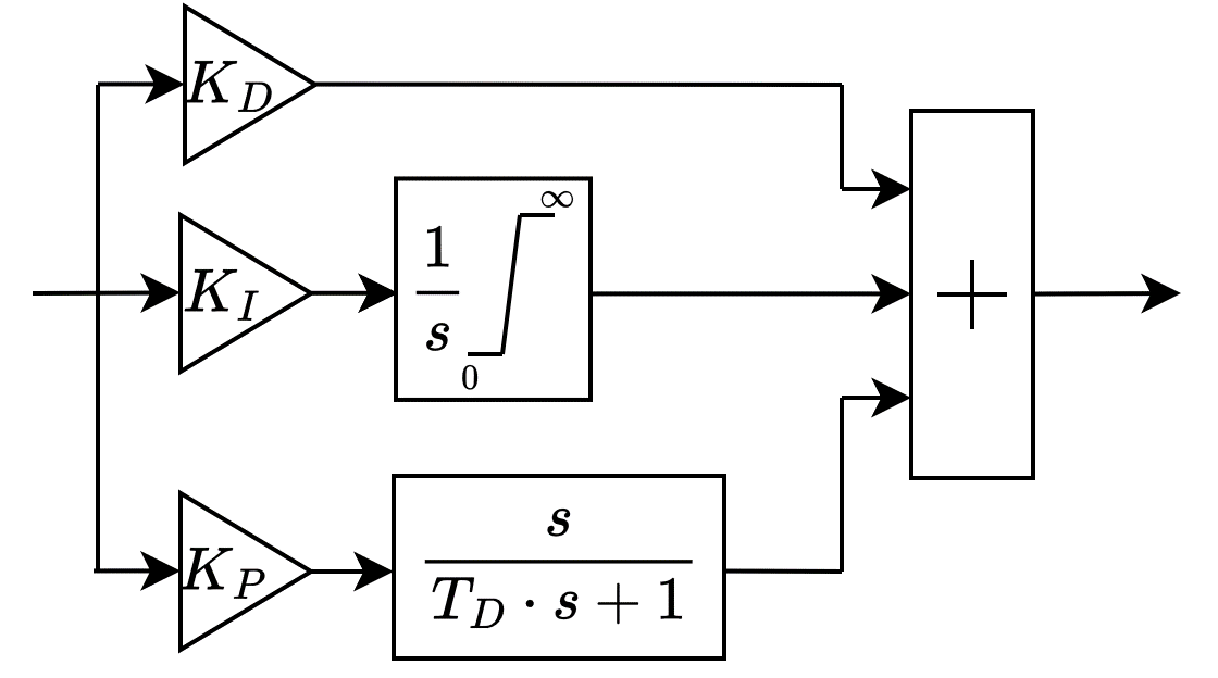
Fig. 3 The block diagram of PID controller implementation#
Note
In the PID controller design, a low-pass filter described by a first-order transfer function is implemented in the differential channel. The filter time constant is specified in the Derivative filter time constant.
Phase generator (sawtoothlike). It is an integrator that resets when the phase reaches a value of \(2\cdot\pi\) and thus forms a sawtoothlike signal at the output. Control signal from PID controller is transmitted to input of this unit.
The input frequency is determined from the PID controller output signal. In its simplest form, it is determined by transferring this signal from \(\frac{rad}{s}\) to Hz. The block implements the ability to enable the limitation of the rate of change of the signal, as well as its filtering after limitation. Use ROCOF limiter of output frequeency and Output frequency filter properties to enable this functionality.
1. Properties#
Property |
Default Value |
Description |
Units of measurement |
|---|---|---|---|
d axis position at the initial time: |
90° behind A axis |
- |
- |
Implementation of phase difference forming: |
Angle between d and q components |
- |
- |
Angle between axes A andq at initial time, available when |
0.0 |
- |
deg |
Angle offset between d and q, available when selecting |
180.0 |
- |
deg |
Minimum frequency, available when selecting |
10.0 |
- |
Hz |
Initial phase |
0.0 |
- |
deg |
60.0 |
- |
Hz |
|
Proportional gain |
180.0 |
- |
- |
Integral gain |
3200.0 |
- |
- |
Derivative gain |
1.0 |
- |
- |
0.001 |
- |
s |
|
Frequency filter cut-off frequency, available when selecting |
25.0 |
- |
Hz |
ROCOF limit for frequency measurement, available when selecting |
1000.0 |
- |
- |
Adaptive gain>, available when selecting |
On |
- |
- |
On |
- |
- |
|
On |
- |
- |
|
On |
- |
- |
|
Sampling type: |
Fundamental project frequency decimation |
- |
- |
Sample time, available when selecting |
0.05 |
- |
s |
Decimation factor of project fundamental discretization frequency, available when selecting |
1 |
- |
- |
Sampling frequency, available when selecting |
20.0 |
- |
Hz |
2. Inputs and outputs#
Parameters |
Input/Output |
Description |
Units of measurement |
Port type |
|---|---|---|---|---|
Phase A input |
Input |
- |
- |
Automation |
Phase B input |
Input |
- |
- |
Automation |
Phase C input |
Input |
- |
- |
Automation |
Frequency |
Output |
- |
Hz |
Automation |
Angle |
Output |
- |
rad |
Automation |
In order to see the connection capabilities of the block, you need to go to page Description of block ports