

Pressure compensator (TL)#
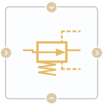
Block appearance in REPEAT VISION#
The Pressure compensator (TL) block has 4 ports:
A and B - hydraulic ports through which liquid flows through the network under consideration;
X and Y - hydraulic ports of the third-party hydraulic network. The characteristics of this network (for example, the dependence of the flow rate on the difference on each component of the network or the network as a whole) are not involved in the calculation of the main hydraulic network, and points X and Y are used only to monitor the pressure in the third-party network using the block in question.
The block describes the flow of liquid through the valve cross-section, which controls the pressure if the current drop at ports X and Y exceeds the setpoint, but does not exceed the maximum pressure.
The maximum pressure is the sum of the setpoint and the control range.
The pressure setpoint can be zero, the control range is strictly greater than zero. The smaller the monitoring range, the faster the valve position changes at pressure change (the control speed increases).
There are two modes of valve operation:
The
Constantmode, the pressure setpoint remains unchanged and is set through the block propertySet pressure drop;The
Controlledmode, the setpoint is set by the external signal via the automation port.
Simulated valve can be:
Normally open (for example, reducing valve), maintaining the downstream pressure not higher than the set one;
Normally closed (for example, safety valve), maintaining the upstream pressure not higher than the set one.
Leakage area is the area of the hole when the valve is fully closed.
Note
Can be set to zero
Maximum area is the area of the hole when the valve is fully open.
Note
Should be set strictly less than valve port area
Provision is made for selecting a pressure recovery option.
Valve opening can be parameterized linearly or using tabular data.
If Opening parametrization is set to Linear, the hole area is a linear function of the piston valve travel distance (1) :
where:
\(A_{orifice}\) - open area;
\(ΔS\) is a piston valve travel distance entered into port S (2) :
\(ΔS_{max}\) is the value of the parameter movement of the piston valve between the closed and open holes;
\(A_{leak}\) - value of parameter Leakage area;
\(A_{max}\) — value of parameter Maximum valve area.
Scaling from \(A_{Leak}\) to \(A_{max}\) is implemented linearly.
If set Opening parametrization to Tabulated, the clock uses piston valve travel vector and parameters Valve area vector, to determine the relationship between \(A_{orifice}\) and \(ΔS\) by interpolation. \(A_{leak}\) and \(A_{max}\) are the first and last parameter Valve area vector respectively.
Law of mass conservation (3) :
Dependence of mass on pressure drop (4) :
where:
\(A_{valve}\) – valve cross-sectional area, [m\(^2\)];
\(A_{port}\) – port cross-sectional area, [m\(^2\)];
\(PR_{loss}\) – loss ratio;
\(\Delta p_{crit}\) – critical pressure drop, [Pa];
\(\Delta p\) – pressure drop between input and output port, [Pa].
Note
Calculated in the model core at each cycle of its operation
Note
Note
For this block \(\Delta p_1\) is defined as the difference between input port 1 and output port, ‘dp2’ is the same for port 2. \(Min_1\) and \(Min_2\) values - mass flows through input ports 1 and 2, respectively, are calculate аrom the values of these two differences.
Calculation of critical drop (5) :
where:
\(C_d\) – recovery factor;
\( u\) – liquid kinematic viscosity, [mm\(^2\)/s];
\(Re_{crit}\) – Critical Reynolds number, the boundary between laminar and turbulent flow.
Calculation of loss coefficients (6) :
Law of conservation of energy (7) :
where:
\(\phi_A\) - energy flow at the input, [W];
\(\phi_B\) - energy flow at the output, [W].
1. Properties#
Property |
Default value |
Description |
Units of measurement |
|---|---|---|---|
Valve specification: |
Normally open |
- |
- |
Constant |
- |
- |
|
Opening parametrization: |
Linear |
- |
- |
Off |
- |
- |
|
Pressure drop set, available when selecting |
500 |
- |
Pa |
Pressure range, available when selecting |
10000 |
- |
Pa |
150 |
- |
- |
|
Discharged coefficient, available when selecting |
0.64 |
- |
- |
Leakage area, available when selecting |
1e-10 |
- |
m\(^2\) |
Maximum valve area, available when selecting |
0.01 |
- |
m\(^2\) |
Port area |
0.1 |
- |
m\(^2\) |
Smoothing factor |
0.01 |
- |
- |
Presure drop vector, available when selecting |
2e5; 4e5; 6e5; 8e5; 1e6; 1.2e6 |
- |
Pa |
Valve area vector, available when selecting |
1e-5; 8e-6; 6e-6; 4e-6; 2e-6; 1e-10 |
- |
m\(^2\) |
2. Inputs and outputs#
Parameters |
Input/Output |
Description |
Units of measurement |
Port type |
|---|---|---|---|---|
Input |
Input |
- |
- |
Thermohydraulics |
Control port X |
Input |
- |
- |
Thermohydraulics |
Control port Y |
Input |
- |
- |
Thermohydraulics |
Pressure drop |
Input |
Available, when |
Pa |
Automation |
Output |
Output |
- |
- |
Thermohydraulics |
In order to see the connection capabilities of the block, you need to go to page Description of block ports