

Permanent magnet synchronous motor#
Block appearance in REPEAT VISION#
The Permanent magnet synchronous motor block is a synchronous electric motor whose inductor consists of permanent magnets.
In order to calculate parameters, a replacement diagram of a synchronous motoris represented in dq-axes Fig. 1:
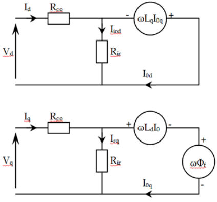
Fig. 1 Replacement diagram of a synchronous motor#
The voltage equations applied to the stator are shown in the formulas below (1) :
where:
\( \psi_{PM}\) - flux linkage generated by the rotor permanent magnets (set by user);
The currents are determined according to the following formulas (2) :
The electromagnetic moment is determined according to the formula (3) :
where 2p - number of pole pairs.
1. Properties#
Property |
Default value |
Description |
Units of measurement |
|---|---|---|---|
Stator resistance |
500e-3 |
– |
Ohm |
Stator inductance d axis |
1e-3 |
– |
H |
Stator inductance q axis |
1e-3 |
– |
H |
Magnets’ flux linkage |
50e-3 |
Parameter that defines the amount of induced flux linkage in stator on one pole pair |
Wb |
Friction coefficient |
100e-3 |
– |
N·m·s |
Inertia |
1 |
Rotor inertia |
kg\(\cdot\) m\(^2\) |
Pole pairs |
1 |
Number of pole pairs |
– |
2. Inputs and outputs#
Parametes |
Input/Output |
Description |
Units of measurement |
Port type |
|---|---|---|---|---|
A |
Input |
Phase A |
– |
Electronics |
B |
Input |
Phase B |
– |
Electronics |
C |
Input |
Phase C |
– |
Electronics |
Applied torque |
Input |
Torque applied to the shaft |
N\(\cdot\) m |
Automation |
Angular velocity |
Output |
Shaft’s angular velocity |
rad/s |
Rotational motion |
Electromagnetic torque |
Output |
Torque produced by electromagnetic field |
N\(\cdot\) m |
Automation |
Current phase A |
Output |
I\(_a\) |
A |
Automation |
Current phase B |
Output |
I\(_b\) |
A |
Automation |
Current phase C |
Output |
I\(_c\) |
A |
Automation |
In order to see the connection capabilities of the block, you need to go to page Description of block ports