

Gate valve (TL)#
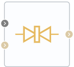
Block appearance in REPEAT VISION#
The Gate valve (TL) block simulates changes in energy and pressure of liquid when passing through the component of thermal hydraulic system - a gate valve that blocks the flow by moving (deltaL) the circular gate, which is set by sum of external signal S and gate offset in the closed position. The S signal increase causes the gate opening, and with S = 0 and Gate offset = 0 the gate is completely closed (1):
At \(\Delta\)L=0, the valve is completely closed;
Hint
when the value of this parameter is increased, it opens.
At \(\Delta\)L≤0, the flow area is equal to the leakage area.
At \(\Delta\)L>d\(_0\), (gate displacement exceeds valve diameter), the flow area is unchanged and maximum.
The block can use smoothing option when Smoothing Factor parameter is > 0 for the \(\Delta\)L parameter at extreme positions (comparable to 0 or d\(_0\), where d\(_0\) is hole diameter in the valve).
The pressure recovery option can also be used in the block in order to connect it, set the parameter Pressure recovery - On.
The area open to the flow at gate retraction is equal to (2):
where d\(_{0}\) - the diameter of the valve hole, [m].
The area shielded by the gate valve in a partially open valve is equal to (3):
where \(\Delta\)l - is the gate displacement, [m], which is the sum of signal at portSandgate position when the hole is fully closed.
If the displacement exceeds the diameter of the hole, the flow area is the sum of the maximum hole area and the leakage area (4):
For any combination of signal at port S and gate displacement is less than 0, the minimum valve area is theleakage area.
Mass flow rate is maintained by the valve (5):
where:
С\(_d\) - discharge coefficient;
A\(_{valve}\) - valve open area, [m\(^2\)];
A\(_{port}\) - is the cross-section area of ports A and B, [m\(^2\)];
\(\bar\rho\) - average density of liquid, [kg/\(m^3\)];
\(\Delta p\) - pressure difference at valve p\(_A\) – p\(_B\), [Pa].
The critical pressure drop, \(\Delta p_{crit}\) , is pressure drop associated with the critical Reynolds number, Re\(_{crit}\), which is the transition point of the flow mode between laminar and turbulent flow (6):
The pressure loss describes a decrease in pressure in the valve due to a decrease in area (7):
Pressure recovery describes a positive pressure change in the valve due to area increase. If you do not want to record this pressure increase, remove Pressure recovery flag. In this case PR\(_{loss}\) = 1.
Law of conservation of mass (8):
Law of conservation of energy (9):
where:
\(\phi_А\) - energy flow at the input, [W];
\(\phi_B\) - energy flow at the output, [W].
1. Properties#
Property |
Default value |
Description |
Units of measurement |
|---|---|---|---|
Off |
- |
- |
|
Orifice diameter |
0.3 |
- |
m |
0 |
- |
m |
|
Leakage area |
1.0e-5 |
- |
m\(^2\) |
Port area |
0.07 |
- |
m\(^2\) |
Critical Reynolds number |
150.0 |
The Reynolds number at which the transition from laminar to turbulent flow occurs |
- |
0.01 |
- |
- |
|
Discharge coefficient, available when selecting |
0.64 |
- |
- |
2. Inputs and outputs#
Parameters |
Input/Output |
Description |
Units of measurement |
Port type |
|---|---|---|---|---|
Displacement |
Input |
- |
m |
Automation |
Input |
Input |
- |
- |
Thermohydraulics |
Output |
Output |
- |
- |
Thermohydraulics |
In order to see the connection capabilities of the block, you need to go to page Description of block ports
3. Примеры использования#
С примерами использования данного блока можно ознакомиться в следующих разделах:
Уроки;
Описание Демо-проектов.
Практическое руководство
Раздел |
Название руководства |
|---|---|
Энергетика |
Development of a model of the industrial circuit system of oil coolers of NPP with WCWR |