

Four way three position valve (TL)#
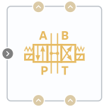
Block appearance in REPEAT VISION#
Four way three position valve (TL) models a valve with four orifices in a thermal-hydraulic network, typically between an actuator, pump, and tank. The valve is controlled by a single spool, the position of which is determined by the signal at port S. The block has two inlets — P and T and two outlets — A and B.
The block consists of four hydraulic orifices paired—PA, PB, TA, and TB. See the mathematical model in the block Hydraulic Orifice (TH).
The flow area of the orifice depends linearly on the spool position and is described by the formula (1):
where:
\(S_{min}\) - parameter Spool min position, [m];
\(\Delta S\) - parameter Spool stroke, [m];
\(A_{max}\) - parameter Maximum area, [m\(^2\)];
\(A_{leak}\) - parameter Leakage area, [m\(^2\)];
\(\epsilon\) - parameter Opening Orientation.
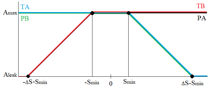
Orifice operation diagram depending on the spool position.#
1. Properties#
Property |
Default Value |
Description |
Units of measurement |
|---|---|---|---|
Area port |
0.001 |
- |
m\(^2\) |
1.0e-4 |
- |
m\(^2\) |
|
1.0e-9 |
- |
m\(^2\) |
|
0.01 |
- |
m |
|
0.05 |
- |
m |
|
Discharge coefficient |
0.64 |
- |
- |
Critical Reynolds number |
150.0 |
The Reynolds number at which the transition from laminar to turbulent flow occurs |
- |
Smoothing factor |
0.01 |
- |
- |
2. Inputs and outputs#
Parameters |
Input/Output |
Description |
Units of measurement |
Port type |
|---|---|---|---|---|
Spool displacement |
Input |
- |
m |
Automation |
Port P |
Input |
- |
- |
Thermohydraulics |
Port T |
Input |
- |
- |
Thermohydraulics |
Port A |
Output |
- |
- |
Thermohydraulics |
Port B |
Output |
- |
- |
Thermohydraulics |
In order to see the connection capabilities of the block, you need to go to page Description of block ports