

Rack and pinion gear#
Block appearance in REPEAT VISION#
Rack and pinion gear block is designed to convert translational motion into rotational motion. This gearing consists of a gear wheel with radius r and a rack, the main parameter of which is the lifting angle \(\alpha\). A negative angle value forms the left thread and a positive angle value forms the right thread.
The input port receives the speed signal in [m/s], the output port receives the angular speed in [rad/s] (see Fig. 1 below). The output port transmits the moment in [N \(\cdot\) m].
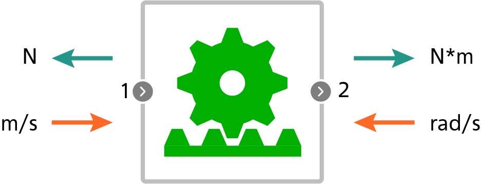
Fig. 1 Rack and pinion gear icon#
The stiffness and damping of the contact surface are necessary to calculate the normal force acting on the threads. Static friction and sliding friction factors shall be specified to account for friction.
In this unit, the “Integrator with reset” friction model is implemented, in which the magnitude of the static friction force depends on the boundary distance of static friction, which is specified in the unit properties.
The resultant force consists of normal and tangent components. Normal force depends on relative speed and distance traveled (1) :
where:
d - damping, [N \(\cdot\) s/m];
k - hardness, [N/m];
v\(_{rel}\) - relative speed, [m/s].
Initially, the transmission is in rest mode, a static friction force is formed at a non-zero relative speed (2) :
In static friction, the tangential force depends on the distance boundary s\(_{boundary}\) (3) :
where:
\(k_{static.}\) - stiffness at static friction, [N/(m/s)];
\(s_{boundary}\) - boundary distance, at overcoming of which sliding mode occurs, [m];
\(c_{static.}\) - coefficient of static friction, [r.u.];
\(v_{rel.tang.}\) - relative speed parallel to screw thread turn surface, [m/s].
In sliding mode, friction is calculated relative to the normal force using the expression (4) :
The Stribeck effect allows a smooth transition between static and dynamic friction. Turn on the Account Stribeck effect toggle switch to take this effect into account. With this configuration, the friction force becomes exponential and is determined by the expression (5) :
The force on the rail is calculated using the expression (6):
The torque on the wheel is calculated using the expression (7) :
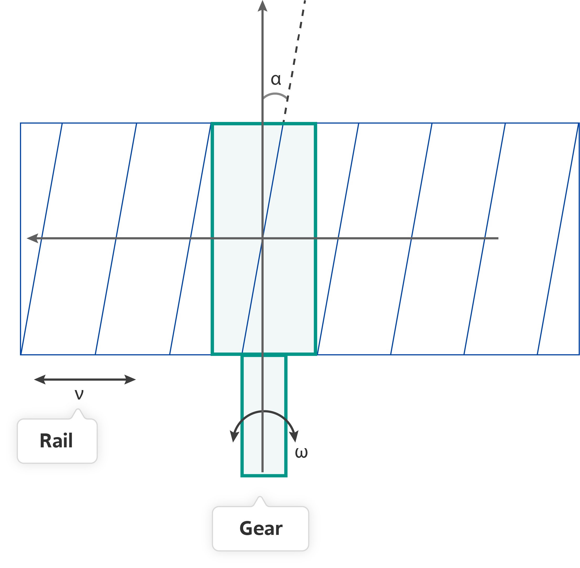
Fig. 2 Rack elevation angle#
1. Properties#
Property |
Default value |
Description |
Units of measurement |
|---|---|---|---|
Pin radius |
0.01 |
- |
m |
Helix angle |
2.0 |
- |
deg |
Contact stiffness |
1000.0 |
- |
N/m |
Contact damping |
1000.0 |
- |
N/(m/s) |
Coulumb friciton coefficient |
0.01 |
- |
r.u. |
Stiction coefficient |
0.02 |
- |
- |
Stiction viscous friction |
1000 |
- |
N/(m/s) |
Stiction displacement threshold |
0.001 |
- |
m |
Off |
- |
- |
|
Stribeck constant, available when |
0.001 |
- |
m/s |
Off |
On(TRUE) - conversion of rotational motion into translational motion; |
- |
2. Inputs and outputs#
Parameters |
Input/Output |
Description |
Units of measurement |
Port type |
|---|---|---|---|---|
Velocity |
Input |
Available when the property |
m/s |
Translational motion |
Angular velocity |
Input |
Available when the property |
rad/s |
Rotational motion |
Torque |
Output |
Available when the property |
N \(\cdot\) m |
Rotational motion |
Force |
Output |
Available when the property |
N |
Translational motion |
In order to see the connection capabilities of the block, you need to go to page Description of block ports