

MOSFET transistor#
Block appearance in REPEAT VISION#
The MOSFET transistor block is a simplified model of a reverse diode field-effect transistor. The equivalent circuit consists of a parallel-connected key and a diode, transistor resistance is determined by the control signal (it is equal to internal resistance at activation, and equal to resistance in the closed state at deactivation).
A signal > 0 shall be sent to the control port to open. The diode model also takes into account the forward bias voltage. The equivalent circuit is shown below Fig. 1:
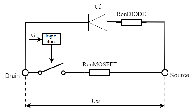
Fig. 1 FET equivalent circuit#
Fig. 2 shows below the transistor CVD (diode - reverse connection, so its activated state is in the 3rd quadrant):
Section 0-7 corresponds to the deactivated transistor state when the control command is g = 0: \(R_T\)=\(R_{clos.MOSFET}\);
The open state of the diode illustrates section 1-2 when voltage drop across at transistor is less than the diode forward bias voltage: \(R_D\)=\(R_{int.Diode}\);
Accordingly, in section 2-4, the diode is in the closed state and its resistance: \(R_D\)=\(R_{clos.Diode}\);
Section 5-6 corresponds to the transistor state when the control command is g > 0: \(R_T\)=\(R_{int.MOSFET}\).
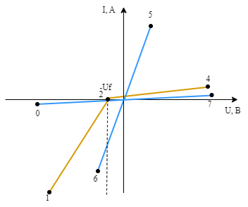
Fig. 2 CVD field-effect transistor#
1. Properties#
Property |
Default Value |
Description |
Units of measurement |
|---|---|---|---|
Internal resistance |
1e-2 |
- |
Om |
MOSFET off state resistance |
1e12 |
- |
Om |
Diode resistance |
1e-2 |
- |
Om |
Diode off state resistance |
1e12 |
- |
Om |
Diode forward voltage |
0.5 |
- |
V |
On |
- |
- |
|
Snubber resistance |
1e6 |
Available, when |
Om |
Snubber capacitance |
1e9 |
Available, when |
F |
2. Inputs and outputs#
Parameters |
Input/Output |
Description |
Units of measurement |
Port type |
|---|---|---|---|---|
Control input |
Input |
- |
- |
Automation |
Drain |
Input |
- |
- |
Electronics |
Source |
Output |
- |
- |
Electronics |
In order to see the connection capabilities of the block, you need to go to page Description of block ports