

Autotransformer#
Block appearance in REPEAT VISION#
The Autotransformer block represents a mathematical modelof an autotransformer - a device for electromagnetic conversionof AC voltage into two other voltage systems in accordance with the specifiedtransformation ratios at constant frequency.
Note
The conversion isnon-ideal due tonatural losses in the steel and windings of the autotransformer.
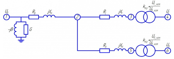
Fig. 1 Equivalent circuit#
The equivalent circuit of an autotransformer (see Fig. 1 above) is identical to the three-beamequivalent circuit of a three-winding transformer and is also suitable forsimulation of steady-state modes and electromechanical transients.
Note
All values of the equivalent circuit parameters are calculated based on the catalog data of the transformer.
Total winding resistances (1):
where (2):
The autotransformers are designed for the typical power and the LV winding is calculated for a power less than the standard power.The ratio between the rated power of the autotransformer and the LV winding power is determined by a coefficient \(\alpha\) equal to the ratio of the LV winding power to the rated power of the transformer (3):
The winding power is usually specified in the autotransformer data sheet.There may be cases when a direct ratio between LV winding power and ratedpower is given, which is equal to the value of the coefficient \(\alpha\), or when there is no data on LV winding power - in this case an average value \(\alpha\) = 0.5 is taken.
To calculate the active resistances of the AV and LV windings, the corresponding short-circuit losses shall be brought to the rated power as follows (4):
where (5):
In some cases, only \(∆P_{scHM}\) losses are known. In such a case, the winding resistances are calculated as follows (6):
The winding reactances are determined from the total and active resistances (7):
The active and reactance of the shunt are calculated based on the catalog values of the no-load experience (8):
1. Properties#
Property |
Default value |
Description |
Units of measurement |
|---|---|---|---|
Rated power |
6 |
Rated power of the transformer primary winding |
MVA |
Rated power of the tertiary winding |
0 |
Rated power of the transformer tertiary winding |
MVA |
Tertiary winding rated voltage |
6.3 |
Rated voltage of the tertiary winding |
kV |
Secondary winding rated voltage |
10 |
Rated voltage of the secondary winding |
kV |
Primary winding rated voltage |
35 |
Rated voltage of the primary winding |
kV |
Short-circuit voltage P-S |
7.5 |
SC voltage with shorted primary and secondary windings as a percentage of the rated voltage |
% |
Short-circuit voltage P-T |
10 |
SC voltage with shorted primary and tertiary windings as a percentage of the rated voltage |
% |
Short-circuit voltage S-T |
16.5 |
SC voltage with shorted secondary and tertiary windings as a percentage of the rated voltage |
% |
Short-circuit power losses P-S |
3 |
SC power with shorted primary and secondary windings |
kW |
Short-circuit power losses P-T |
4 |
SC power with shorted primary and tertiary windings |
kW |
Short-circuit power losses S-T |
5 |
SC power with shorted secondary and tertiary windings |
kW |
Incorporate no load power losses |
Off |
– |
– |
No load power losses |
No load power losses |
idle power losses (iron losses) |
kW |
No-load current |
0.6 |
idle current as a percentage of the rated current of the HV winding |
% |
2. Inputs and outputs#
Parameters |
Input/Output |
Description |
Units of measurement |
Port type |
|---|---|---|---|---|
Input voltage of the primary winding |
Input |
– |
V |
Electrocity |
Output voltage of the secondary winding |
Output |
– |
V |
Electrocity |
Output voltage of the tertiary winding |
Output |
– |
V |
Electrocity |
In order to see the connection capabilities of the block, you need to go to page Description of block ports