

Single-phase three windings transformer#
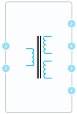
Block appearance in REPEAT VISION#
The Single-phase three windings transformer block is a linear model of a single-phase three-winding transformer. The transformer equivalent circuit is shown in Fig. 1:
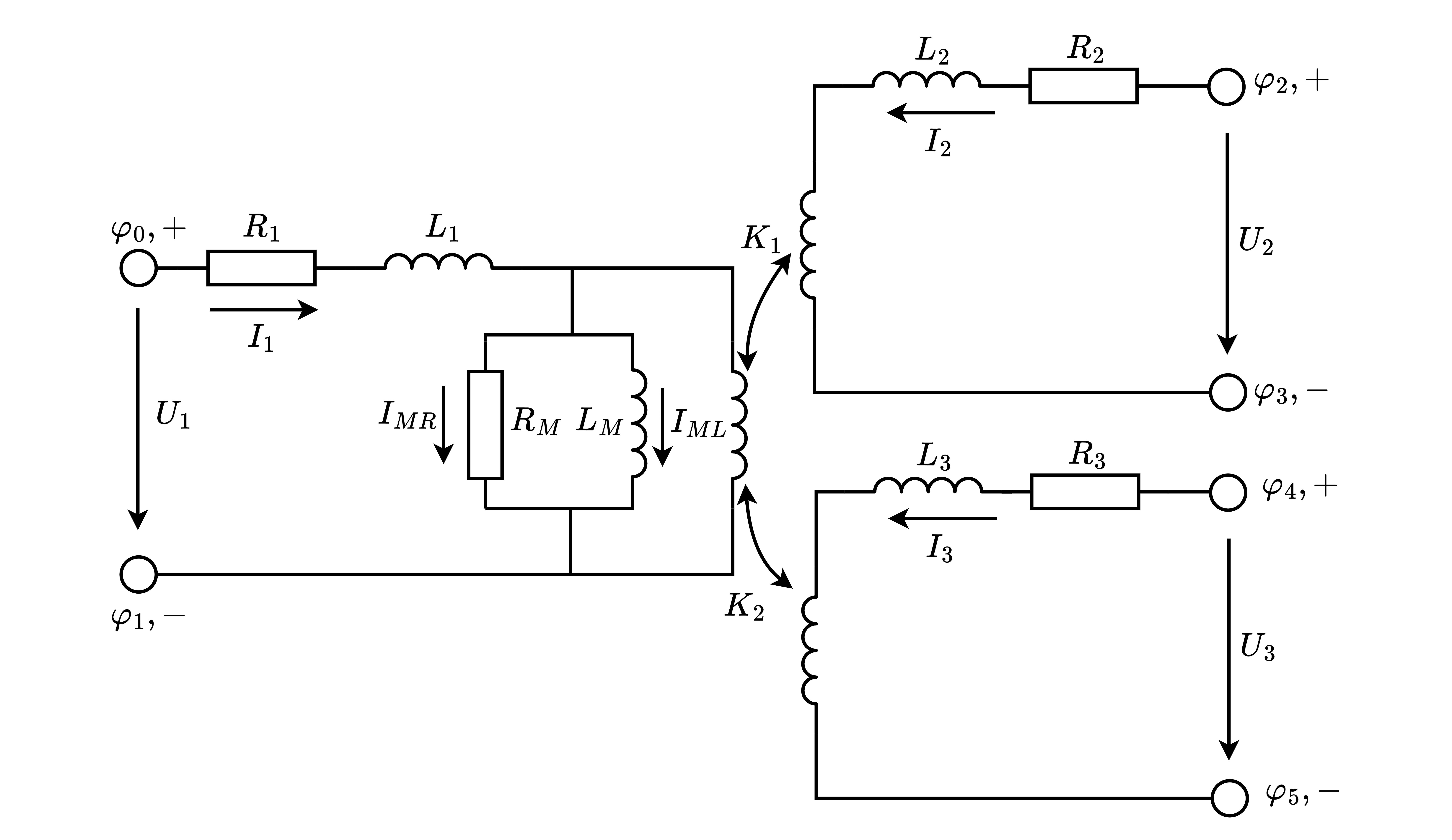
Fig. 1 Transformer equivalent circuit#
This model is based on an ideal transformer, the primary winding of which is connected to the magnetization branch with parameters \(R_M\), \(L_M\) and active-inductive resistance with parameters \(R_1\), \(L_1\). Secondary winding is connected to active-inductive resistance with parameters \(R_2\), \(L_2\), and tertiary winding is connected to active-inductive resistance with parameters \(R_3\), \(L_3\).
Taking into account the above mentioned circuit, the three-winding single-phase transformer is described by the following system of equations (1):
where:
\(U_1\), \(U_2\), \(U_3\) - voltages of primary, secondary and tertiary windings, respectively, [V];
\(I_1\), \(I_2\), \(I_3\) - currents of primary, secondary and tertiary windings respectively, [A];
\(I_{ML}\) - inductive component of magnetization branch current, [A];
\(I_{MR}\) - active component of magnetization branch current, [A];
\(U_M\) - voltage on the magnetization branch, [V];
\(R_1\), \(R_2\), \(R_3\) - active resistances of primary, secondary and tertiary windings respectively, [Ohm];
\(L_1\), \(L_2\), \(L_3\) - inductance of primary, secondary and tertiary windings respectively, [H];
\(R_M\) - active resistance of the magnetization branch, [Ohm];
\(L_M\) - inductance of the magnetization branch, [H];
\(К_1\) - transformation ratio of ideal transformer between primary and secondary windings;
\(К_2\) - transformation ratio of ideal transformer between secondary and tertiary windings.
The model has various ways of model parameters:
Setting of parameters in SI system (then it is necessary to set only the winding parameters (rated voltages, [V], active resistances, [Ohm] and inductance, [H]));
Setting of parameters in relative units (then it is necessary to set only winding parameters (rated voltages, [V], active resistances, [r.u.] and inductance, [r.u.]));
Set the catalog parameters (the parameters of the equivalent circuit will be calculated automatically).
The procedure for calculating the parameters of the equivalent circuit from relative units and catalog data is given in the corresponding article.
1. Properties#
Property |
Default value |
Description |
Units of measurement |
|---|---|---|---|
Method of specifying model parameters: |
SI |
- |
- |
Primary winding parameters, [U\(_{1ф}\); R\(_1\); L\(_1\)] |
735000.0;0.3218;0.005856; |
Available, when |
V; Ohm; H |
Secondary winding parameters, [U\(_{2ф}\); R\(_2\); L\(_2\)] |
315000.0;0.07938;0.0084225; |
Available, when |
V; Ohm; H |
Tertiary winding parameters, [U\(_{3ф}\); R\(_3\); L\(_3\)] |
315000.0;0.07938;0.0084225; |
Available, when |
V; Ohm; H |
Magnetizing branch parameters, [R\(_m\); L\(_m\)] |
1080400.0;2866.0; |
Available, when |
Ohm; H |
Nominal power |
2.5e8 |
Available, when |
VA |
Nominal frequency |
60.0 |
Available, when |
Hz |
Primary winding parameters, [U\(_{1ф}\); R\(_1\); L\(_1\)] |
735000.0;0.002;0.08; |
Available, when |
V; r.u.; r.u. |
Secondary winding parameters, [U\(_{2ф}\); R\(_2\); L\(_2\)] |
315000.0;0.002;0.08; |
Available, when |
V; r.u.; r.u. |
Tertiary winding parameters, [U\(_{3ф}\); R\(_3\); L\(_3\)] |
315000.0;0.002;0.08; |
Available, when |
V; r.u.; r.u. |
Magnetizing branch parameters, [R\(_m\); L\(_m\)] |
500.0;500.0; |
Available, when |
r.u.; r.u. |
Nominal voltage of primary winding |
230000.0 |
Available, when |
V |
Nominal voltage of secondary winding |
115000.0 |
Available, when |
V |
Nominal voltage of tertiary winding |
115000.0 |
Available, when |
V |
Nominal HV - LV short-circuit losses |
35000.0 |
Available, when |
W |
Nominal HV -MV short-circuit losses |
35000.0 |
Available, when |
W |
Nominal MV -LV short-circuit losses |
35000.00 |
Available, when |
W |
Nominal HV - LV impedance voltage |
10.5 |
Available, when |
% |
Nominal HV - MV impedance voltage |
10.5 |
Available, when |
% |
Nominal MV - LV impedance voltage |
10.5 |
Available, when |
% |
Nominal no load losses |
10000.0 |
Available, when |
W |
Nominal no load current |
0.5 |
Available, when |
% |
Initial currents of windings, [I\(_1\); I\(_2\); I\(_3\)] |
0.0;0.0;0.0; |
- |
A |
Initial values of magnetizing branch current and voltage, [I\(_M\); U\(_M\)] |
0.0;0.0; |
- |
А; V |
2. Inputs and outputs#
Parameters |
Input/Output |
Description |
Units of measurement |
Port type |
|---|---|---|---|---|
Primary winding, + |
Input |
- |
- |
Electronics |
Primary winding, - |
Output |
- |
- |
Electronics |
Secondary winding, + |
Output |
- |
- |
Electronics |
Secondary winding, - |
Input |
- |
- |
Electronics |
Tertiary winding, + |
Output |
- |
- |
Electronics |
Tertiary winding, - |
Input |
- |
- |
Electronics |
In order to see the connection capabilities of the block, you need to go to page Description of block ports