

Flashing LED#
Block appearance in REPEAT VISION#
The Flashing LED block represents a model of a physical LED, with variable flashing frequency and range of luminescence.
Note
The block properties specify the lower boundary and upper boundary values of the specified blink range, the boundary point is defined by the Continuous blinking frequency property. The amplitude of one blink equals to 1.
Note
a) When Boundary point is in the blinking range, from the beginning of the range to the boundary point the output signal is 1, from the boundary point to the end of the range the output signal is blinking, Fig. 1. _ Initial conditions _:
lower boundary |
10 |
|---|---|
upper boundary |
25 |
boundary point |
20 |
blinking frequency |
1 [Hz] |
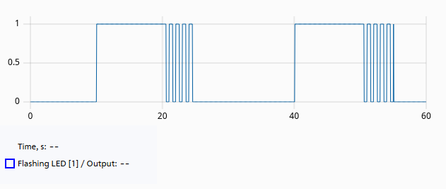
Fig. 1 Case “a”#
Note
b) When the Boundary point is before the range, then from the limit point to the end of the range the output signal is a blinking signal, Fig. 2. Initial conditions:
lower boundary |
10 |
|---|---|
upper boundary |
25 |
boundary point |
5 |
blinking frequency |
1 [Hz] |
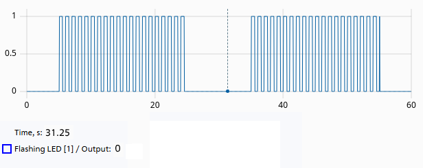
Fig. 1 Case “b”#
Note
c) When the Boundary point is after the range, then the output signal within the range is 1, Fig. 3. Initial conditions:
lower boundary |
10 |
|---|---|
upper boundary |
25 |
boundary point |
30 |
blinking frequency |
1 [Hz] |
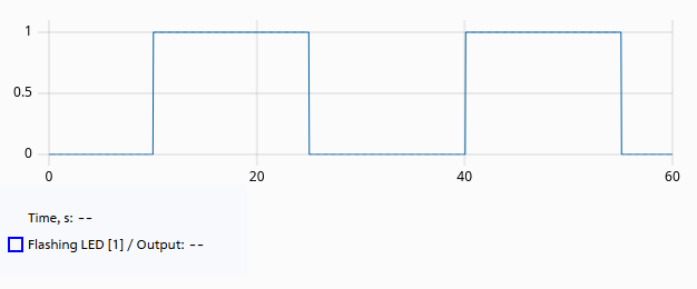
Fig. 1 Case “c”#
1. Properties#
Property |
Default Value |
Description |
Units of measurement |
|---|---|---|---|
0 |
- |
- |
|
2 |
- |
- |
|
3 |
- |
- |
|
1 |
- |
Hz |
2. Inputs and outputs#
Parameters |
Input/Output |
Description |
Units of measurement |
Port type |
|---|---|---|---|---|
Input signal |
Input |
- |
- |
Automation |
Output |
Output |
- |
- |
Automation |
In order to see the connection capabilities of the block, you need to go to page Description of block ports