

Shuttle valve (IH)#
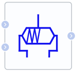
Block appearance in REPEAT VISION#
The Shuttle valve (IH) block simulates the operation of the corresponding component in a hydraulic network, which has two hydraulic inputs, one hydraulic output and operates according to the following principle:
Using the properties of the block, the user sets two pressure setpoints \(dpSet_1\) (Input port 2 closed pressure property) and \(dpSet_2\) (Input port 1 closed pressure property), the first of which is less than the second one. With these setpoints, each cycle of the model is compared with the pressure drop between the two input ports named dp12:
if
dp12drop is less thandpSet1set point, only input port 1 is fully opened and port 2 is completely closed;if
dp12drop is greater thandpSet2second setpoint - only input port 2 is fully opened and port 1 is completely closed;if the differential value is between two setpoints, both input ports are opened, but not completely - the sum of the flow areas through the input ports \(A_{valve1}\) and \(A_{valve2}\) is equal to [maximum valve section area] (#title3) \(A_{max}\). title3The distribution of flows through ports 1 and 2 depends on the deviation of the actual pressure drop between these ports from
dpSet1anddpSet2setpoints - the method for calculating actual areas is given below.
Law of mass conservation (1):
Dependence of mass on pressure drop (2):
where:
\(A_{valve}\) – valve cross-sectional area, [m\(^2\)];
\(A_{port}\) – port cross-sectional area, [m\(^2\)];
\(PR_{loss}\) – loss ratio;
\(\Delta p_{crit}\) – critical pressure drop, [Pa];
\(\Delta p\) – pressure drop between input and output port, [Pa];
Note
Calculated in the model core at each cycle of its operation
Note
Note
For this block, dp1 is defined as the difference between input port 1 and output port, ‘dp2’ is the same for port 2. \(Min_1\) and \(Min_2\) values - mass flows through input ports 1 and 2, respectively, are calculate аrom the values of these two differences.
Calculation of critical drop (3):
where:
\(C_d\) – recovery factor;
\( u\) – liquid kinematic viscosity, [mm\(^2\)/s];
\(Re_{crit}\) – Critical Reynolds number, the boundary between laminar and turbulent flow.
Calculation of loss ratios(4):
Сalculation of valve cross-section area
When liquid flows through input port 1, the flow cross-section area \(A_{valve1}\) is calculated as (5):
where:
\(A_{max}\) – maximum valve cross-sectional area, [m\(^2\)];
\(A_{leak}\) – leakage area, [m\(^2\)];
\(A_{valve2}\) – cross-sectional area of liquid flow through input port 2, [m\(^2\)].
Moreover, the flow cross-sectional area \(A_{valve2}\) is calculated as (6):
Normalized pressure \(P_{norm}\) is calculated as follows (7):
where:
dp12 – pressure drop between inlet ports 1 and 2, [Pa];
\(dpSet_1\) – input ports drop setpoint, below which only input port 1 is open;
\(dpSet_2\) – input ports drop setpoint, above which only input port 2 is open.
1. Properties#
Property |
Default Value |
Description |
Units of measurement |
|---|---|---|---|
-10000.0 |
- |
Pa |
|
10000.0 |
- |
Pa |
|
1.0E-4 |
- |
m\(^2\) |
|
1.0E-10 |
- |
m\(^2\) |
|
0.09 |
- |
m\(^2\) |
|
Discharge coefficient, available when selecting |
0.64 |
- |
- |
150 |
- |
- |
|
Smoothing factor |
0.01 |
- |
- |
On |
- |
- |
2. Inputs and outputs#
Parameters |
Input/Output |
Description |
Units of measurement |
Port type |
|---|---|---|---|---|
Input (port 1) |
Input |
- |
- |
Isothermal Hydraulics |
Input (port 2) |
Input |
- |
- |
Isothermal Hydraulics |
Output |
Output |
- |
- |
Isothermal Hydraulics |
In order to see the connection capabilities of the block, you need to go to page Description of block ports