

Three-phase circuit parameter meter (U, I, P, S, PF)#
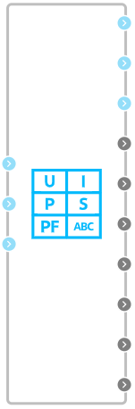
Block appearance in REPEAT VISION#
The Three-phase circuit parameter meter (U, I, P, S, PF) block is used to calculate several parameters of an electrical three-phase three-wire circuit.
Note
The outputs of the block with calculated signals are represented as vectors, so they must be connected to the Demux block with the corresponding number of outputs.
The circuit parameters are calculated based on the following measured values:
instantaneous values of line voltages \(u_{AB}, u_{BC}, u_{CA}\), which are determined using voltmeters connected between the corresponding phases;
instantaneous values of phase currents \(i_A, i_B, i_C\), which are determined using ammeters on the corresponding phases.
The block calculates the following parameters:
effective values of phase currents according to formulas (1) :
instantaneous values of phase voltages according to formulas (2) :
effective values of phase voltages according to formulas (3):
active power of each phase and the sum of the phases according to the formulas (4) :
the total power of each phase and the sum of the phases according to the formulas (5) :
phase power factor according to formulas (6) :
1. Properties#
Property |
Default Value |
Description |
Units of measurement |
|---|---|---|---|
Fundamental harmonic frequency |
50 |
– |
Hz |
2. Inputs and outputs#
Parameters |
Input/Output |
Description |
Units of measurement |
Port type |
|---|---|---|---|---|
A |
Input |
Phase A input |
– |
Electronics |
B |
Input |
Phase B input |
– |
Electronics |
C |
Input |
Phase C input |
– |
Electronics |
a |
Output |
Phase A output |
– |
Electronics |
b |
Output |
Phase B output |
– |
Electronics |
c |
Output |
Phase B output |
– |
Electronics |
Instantaneous values of phase currents |
Output |
Vector of three signals: \(i_A, i_B, i_C\) |
А |
Automation |
Effective values of phase currents |
Output |
Vector of three signals: \(I_{Arms}, I_{Brms}, I_{Crms}\) |
А |
Automation |
Instantaneous values of phase voltages |
Output |
Vector of three signals: \(u_A, u_B, u_C\) |
V |
Automation |
Effective values of phase voltages |
Output |
Vector of three signals: \(U_{Arms}, U_{Brms}, U_{Crms}\) |
V |
Automation |
Active power |
Output |
Vector of four signals: \(P_A, P_B, P_C, P_{\Sigma}\) |
W |
Automation |
Apparent power |
Output |
Vector of four signals: \(S_A, S_B, S_C, S_{\Sigma}\) |
VA |
Automation |
Power factor |
Output |
Vector of three signals: \(K_{MA}, K_{MB}, K_{MC}\) |
p.u. |
Automation |
Note
To separate vector signals, it is necessary to use a demultiplexer.
In order to see the connection capabilities of the block, you need to go to page Description of block ports