

Infinite impulse-response filter (frequency controlled)#
Block appearance in REPEAT VISION#
The Infinite impulse-response filter (frequency controlled) block implements the model of filter with infinite pulse characteristic (IIR filter).
The transfer function of IIR filter is as follows (1):
where
\(b_N\) – direct connection coefficients that are applied to the input signal;
\(a_M\) – feedback coefficients applied to the output signal;
\(z^{-N}\) – signal delay for N-samples;
N and M are the number of delay lines for input and output signals.
The maximum value determines the order of the filter.
The structural diagram of IIR filter is shown in the Fig. 1:
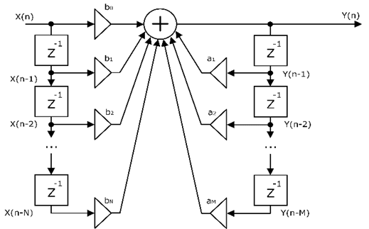
Fig. 1 The structural diagram of IIR filter#
The block allows to set up several types of filters:
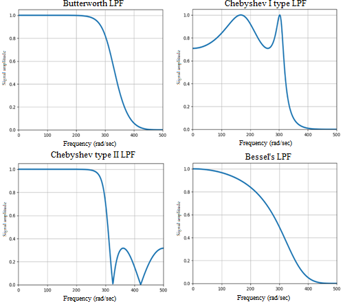
Butterworth filter – the amplitude-frequency characteristic (AFC) of the filter is as smooth as possible at pass band frequencies and decreases to almost zero at suppression band frequencies.
Type I Chebyshev filter - a distinctive feature of the filter is the presence of significant AFC at bandwidth frequencies.
Type II Chebyshev filter - a distinctive feature of the filter is the presence of significant AFC at frequencies of suppression band.
Pulsation index - determines the amplitude of pulsations in the passband/suppression.
Bessel filter - characterized by very gentle areas of AFC in the transition band.
On the Fig. 2 shows AFC of the specified types of filters:
The block allows to select one of the types of filtering:
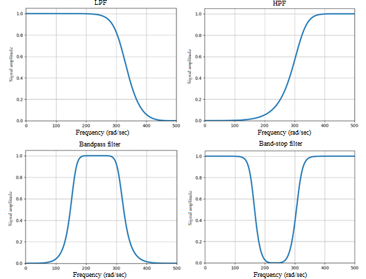
Low pass filter - passes frequencies below the upper cut-off frequency.
High-pass filter - passes frequencies above the lower cut-off frequency.
Bandpass filter – passes the frequency band between the lower and upper cut-off frequencies.
Band-stop filter - does not pass frequencies between the lower and upper cut-off frequencies, but passes vibrations that go beyond these frequencies.
Note
The cut-off frequency shall be less than the Nyquist frequency (half the design sampling frequency).
On the Fig. 3 shows AFC for different types of filtration:
The block allows to specify three different types of sampling:
Fundamental project frequency decimation - the output signal has a sampling rate k times less than the sampling rate of the project (the inverse of the integration step). Here, k is a given design fundamental sampling rate decimation factor, k ≥ 1.
Sampling time is the interval between time points at which the input signal values are sampled. The value of the specified sampling period shall be a multiple of the integration step specified in the project.
Sampling frequency - sampling rate of input signal values. The value of the specified sampling frequency shall be a divider of the sampling frequency specified in the design (the value opposite to the integration step).
1. Properties#
Property |
Default Value |
Description |
Units of measurement |
|---|---|---|---|
Filter type: |
Butterworth filter |
- |
- |
Pass type: |
Low-pass filter |
- |
- |
Filter order |
4 |
- |
- |
High cutoff, available when selecting |
5.0 |
- |
Hz |
Low cutoff, available when selecting |
2.0 |
- |
Hz |
Sampling type: |
- |
- |
|
Decimation factor of project fundamental discretization frequency, available when selecting |
2 |
- |
- |
Sample time, available when selecting |
0.05 |
- |
s |
Sampling frequency, available when selecting |
5.0 |
- |
Hz |
2. Inputs and outputs#
Parameters |
Input/Output |
Description |
Units of measurement |
Port type |
|---|---|---|---|---|
Original signal |
Input |
- |
- |
Automation |
Filtered signal |
Output |
- |
- |
Automation |
In order to see the connection capabilities of the block, you need to go to page Description of block ports