

Cage induction motor#
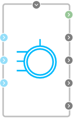
Block appearance in REPEAT VISION#
The Cage induction motor block implements a generalized unsteady model of asynchronous motor with short circuit rotor, without taking saturation into account. The calculation uses a fixed two-axis system \(\alpha\beta\). The Clarke transformation is used to move to the corresponding coordinates (1):
The basic equations for flux coupling and voltage are (2):
where:
\(L_S = L_{1s} + L_m , L_R = L_{1R} + L_m \) - stator and rotor natural inductances;
\(L_m\) - mutual inductance between stator and rotor;
\(\omega_r\) - rotor rotation frequency;
\(p\) - number of pole pairs.
The current, voltage and flux coupling parameters in these equations are in the form of a spatial vector.
The coupling of moment, flux coupling and current is described by the following equation (3):
The basic equation of an asynchronous motor motion is described by the law of moments equilibrium on the machine shaft (4):
where:
\(J\) - inertia moment on the machine shaft, taking into account the inertia of both the machine and the inertia of the working mechanism and the gearbox reduced to the shaft;
\(\omega_m\) - angular speed of the machine shaft;
\(M_C\) - resistance moment of the working mechanism, driven to the shaft.
1. Properties#
Property |
Default value |
Description |
Units of measurement |
|---|---|---|---|
Source frequency |
50 |
Frequency of the power supply |
Hz |
Stator resistance |
500e-3 |
– |
Ohm |
Stator leakage inductance |
1e-3 |
– |
H |
Rotor leakage inductance |
1.8e-3 |
– |
H |
Magnetizing inductance |
50e-3 |
– |
H |
Rotor resistance |
1 |
– |
Ohm |
Friction coefficient |
100e-3 |
– |
– |
Inertia moment |
1 |
Rotor moment of inertia |
kg\(\cdot\) m\(^2\) |
Number of magnetic pole pairs |
1 |
Number of pairs of magnetic poles for stator winding |
– |
2. Inputs and outputs#
Parameters |
Input/Output |
Description |
Units of measurement |
Port type |
|---|---|---|---|---|
A |
Input |
- |
В |
Electronics |
B |
Input |
- |
В |
Electronics |
C |
Input |
- |
В |
Electronics |
Applied torque |
Input |
External resistance torque on the shaft |
N\(\cdot\) m |
Automation |
Angular frequency |
Output |
Angular frequency of rotation of the shaft |
rad/s |
Rotational motion |
Electromagnetic torque |
Output |
The moment of force on the shaft created by the electromagnetic field of the machine |
N\(\cdot\) m |
Automation |
Phase A current |
Output |
I\(_a\) |
A |
Automation |
Phase B current |
Output |
I\(_b\) |
A |
Automation |
Phase C current |
Output |
I\(_c\) |
A |
Automation |
In order to see the connection capabilities of the block, you need to go to page Description of block ports