

Three-phase three windings transformer#
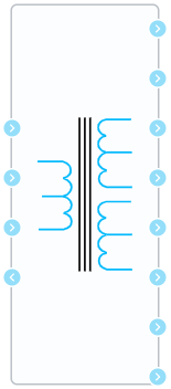
Block appearance in REPEAT VISION#
The Three-phase three windings transformer block is a model of a three-phase three winding transformer.
Model description
The model presented in the block is represented by three single-phase transformers with three windings connected to each other in a user-selected way. The model is symmetrical, the phase parameters are taken the same for each of three phases and are determined in one of three ways. So, setting parameters of equivalent circuit is possible in SI system (then the user needs to enter windings parameters on their own (rated linear voltages, [V], resistances, [Ohm] and inductance, [H])), in relative units (then the user needs to enter transformer parameters (rated linear voltages, [V], resistance, [r.u.], inductance, [r.u.], as well as nominal power, [VA] and rated frequency, [Hz])), as well as by entering the catalog parameters of the transformer (in this case, the equivalent circuit parameters will be calculated automatically from the data provided).
The procedure for calculating the equivalent circuit parameters from relative units and catalog data is described in the corresponding article “Procedure for calculating the parameters of transformer models”.
Selecting the desired winding connection group
Within the block it is possible to select the required circuit of transformer windings. Each winding can be connected by one of two circuits:
“star” (this circuit is denoted by Y) - the ends of the phase windings are connected at one point;
“triangle”-1 (the circuit is denoted by D1) - the end of the winding of each phase is connected to the beginning of the winding of the next one (end of A - with the beginning of B, end of B - with the beginning of C, end of C - with the beginning of A);
“triangle”-11 (the circuit is denoted by D11) - the end of the winding of each phase is connected to the beginning of the winding of the previous one (end of A - with the beginning of C, end of B - with the beginning of A, end of C - with the beginning of B).
The Fig. 1 below shows the directions of current flow in the windings depending on the circuit and group of connections.
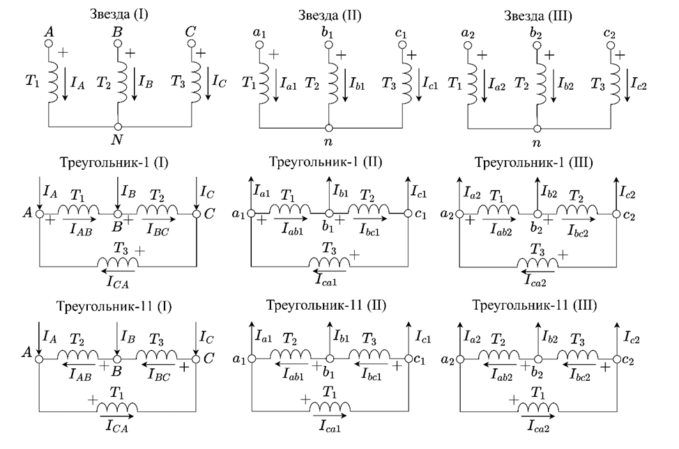
Fig. 1 Directions of current flow in the windings#
The choice of the necessary connection circuit of windings is presented by the following options:Y/Y/Y, Y/Y/D-1, Y/Y/D-11, Y/D-1/Y, Y/D-1/D-1, Y/D-1/D-11, Y/D-11/Y, Y/D-11/D-1, Y/D-11/D-11, D-1/D-1/Y, D-1/D-1/D-1, D-1/D-1/D-11, D-1/Y/Y, D-1/Y/D-1, D-1/Y/D-11, D-1/D-11/Y, D-1/D-11/D-1, D-1/D-11/D-11, D-11/D-11/Y, D-11/D-11/D-1, D-11/D-11/D-11, D-11/Y/Y, D-11/Y/D-1, D-11/Y/D-11, D-11/D-1/Y, D-11/D-1/D-1, D-11/D-1/D-11. The influence of the winding connection group on the transformation ratio is described in the article “Procedure for calculating parameters of transformer models” and is automatically taken into account in the block.
The given connection circuits make it possible to provide various shifts of phase EMF from 0 to +/-60 degrees with step of 30 degrees. It is possible to implement an additional shift of +/- 120 degrees by changing the order of connecting outputs of winding D to c
Group of connections |
Phase shift, degrees |
Winding 1 and 2 (3) connection circuit and group |
Circuit and group of connections 1 of block winding |
Circuit and group of connections 2 (3) of block winding |
Procedure for connecting the outputs of winding connected in D to circuit phases |
|---|---|---|---|---|---|
0 |
0 |
Y/Y-0 |
Y |
Y |
- |
0 |
0 |
D/D-0 |
D-1 |
D-1 |
abc |
1 |
-30 |
Y/D-1 |
Y |
D-1 |
abc |
1 |
-30 |
D/Y-1 |
D-11 |
Y |
abc |
2 |
-60 |
D/D-2 |
D-11 |
D-1 |
abc |
5 |
-150 |
Y/D-5 |
Y |
D-1 |
bca |
5 |
-150 |
D/Y-5 |
D-11 |
Y |
cab |
7 |
+150 |
Y/D-7 |
Y |
D-11 |
cab |
7 |
+150 |
D/Y-7 |
D-1 |
Y |
bca |
10 |
+60 |
D/D-2 |
D-1 |
D-11 |
abc |
11 |
+30 |
Y/D-11 |
Y |
D-11 |
abc |
11 |
+30 |
D/Y-11 |
D-1 |
Y |
abc |
1. Properties#
Property |
Default value |
Description |
Units of measurement |
|---|---|---|---|
Method of specifying model parameters: |
SI |
- |
- |
Primary windings connection scheme: |
Y |
- |
- |
Secondary windings connection scheme: |
Y |
- |
- |
Tertiary windings connection scheme: |
Y |
- |
- |
Primary winding parameters, U\(_{1l}\); R\(_1\); L\(_1\) |
230000.0;4.3218;0.45856 |
Available, when |
V; Ohm; H |
Secondary winding parameters, U\(_{2l}\); R\(_2\); L\(_2\) |
115000.0;0.7938;0.084225 |
Available, when |
V; Ohm; H |
Tertiary winding parameters, U\(_{3l}\); R\(_3\); L\(_3\) |
35000.0;0.7938;0.084225 |
Available, when |
V; Ohm; H |
Magnetization branch parameters, R\(_m\); L\(_m\) |
1080400.0;2866.0 |
Available, when |
Ohm; H |
Nominal power |
2.5E8 |
Available, when |
VA |
Nominal frequency |
50.0 |
Available, when |
Hz |
Primary winding parameters, U\(_{1l}\); R\(_1\); L\(_1\) |
230000.0;0.02;0.68; |
Available, when |
V; r.u.; r.u |
Secondary winding parameters, U\(_{2l}\); R\(_2\); L\(_2\) |
115000.0;0.02;0.68; |
Available, when |
V; r.u.; r.u |
Tertiary winding parameters, U\(_{3l}\); R\(_3\); L\(_3\) |
35000.0;0.02;0.68; |
Available, when |
V; r.u.; r.u |
Magnetization branch parameters, R\(_m\); L\(_m\) |
500.0;500.0; |
Available, when |
r.u.; r.u |
Nominal voltage of primary winding |
230000.0 |
Available, when |
V |
Nominal voltage of secondary winding |
115000.0 |
Available, when |
V |
Nominal voltage of tertiary winding |
115000.0 |
Available, when |
V |
Nominal HV - LV short-circuit losses |
35000.0 |
Available, when |
W |
Nominal HV - MV short-circuit losses |
35000.0 |
Available, when |
W |
Nominal MV - LV short-circuit losses |
35000.0 |
Available, when |
W |
Nominal HV - LV impedance voltage |
10.5 |
Available, when |
% |
Nominal HV - MV impedance voltage |
10.5 |
Available, when |
% |
Nominal MV - LV impedance voltage |
10.5 |
Available, when |
% |
Nominal no load losses |
10000.0 |
Available, when |
W |
Nominal no load current |
0.5 |
Available, when |
% |
Initial currents of phase A windings, [I\(_{1А}\);I\(_{2А}\);I\(_{3А}]\) |
0.0;0.0;0.0 |
- |
А |
Initial currents of phase B windings, [I\(_{1B}\);I\(_{2B}\);I\(_{3B}]\) |
0.0;0.0;0.0 |
- |
А |
Initial currents of phase C windings, [I\(_{1C}\);I\(_{2C}\);I\(_{3C}\)] |
0.0;0.0;0.0 |
- |
А |
Initial values of phase A magnetization branch current and voltage, [I\(_{MА}\); U\(_{MА}\)] |
0.0;0.0 |
- |
A; V |
Initial values of phase B magnetization branch current and voltage, [I\(_{MB}\); U\(_{MB}\)] |
0.0;0.0 |
- |
A; V |
Initial values of phase C magnetization branch current and voltage, [I\(_{MC}\); U\(_{MC}\)] |
0.0;0.0 |
- |
A; V |
2. Inputs and outputs#
Parameters |
Input/Output |
Description |
Units of measurement |
Port type |
|---|---|---|---|---|
А |
Input |
- |
- |
Electronics |
V |
Input |
- |
- |
Electronics |
С |
Input |
- |
- |
Electronics |
N |
Output |
Available, when |
- |
Electronics |
a\(_2\) |
Output |
- |
- |
Electronics |
b\(_2\) |
Output |
- |
- |
Electronics |
c\(_2\) |
Output |
- |
- |
Electronics |
n\(_2\) |
Output |
Available, when |
- |
Electronics |
a\(_3\) |
Output |
- |
- |
Electronics |
b\(_3\) |
Output |
- |
- |
Electronics |
c\(_3\) |
Output |
- |
- |
Electronics |
n\(_3\) |
Output |
Available, when |
- |
Electronics |
In order to see the connection capabilities of the block, you need to go to page Description of block ports
3. Examples of use#
Examples of using this block can be found in the following sections:
Tutorials
Library |
Tutorial name |
|---|---|
Electronics |