

Three-phase transmission line (multi-section)#
Block appearance in REPEAT VISION#
The Three-phase transmission line (multi-section) block implements a mathematical model of a three-phase power transmission line (PTL) using a chain equivalent circuit to take into account the uniform distribution of line parameters along the length [1]. Depending on the value of the Section model property, the PTL section is represented by a Pi section (Fig. 1, a) or T section (Fig. 1, b) equivalent circuit.
The maximum number of sections is 100.
Note
When interpreting the results of sensor readings, it is necessary to take into account that non-zero readings appear when a number of conditions are met:
If the
Number of sectionsproperty has a value greater than 1, then non-zero values will only be in the current and voltage sensors at the ends of the line.If the
Number of sectionsproperty is equal to 1, non-zero values will also be in theLine voltage drop,Line currentsensors, as well as in the capacitive current and active conductivity current sensors.
when the value of the
Section modelproperty isPi section– in the sensors at the beginning and end of the line;when the value of the
Section modelproperty isT section– in sensors in the middle of the line.
In active conductivity current sensors, non-zero values will appear only if the
Enable conductanceproperty is active.
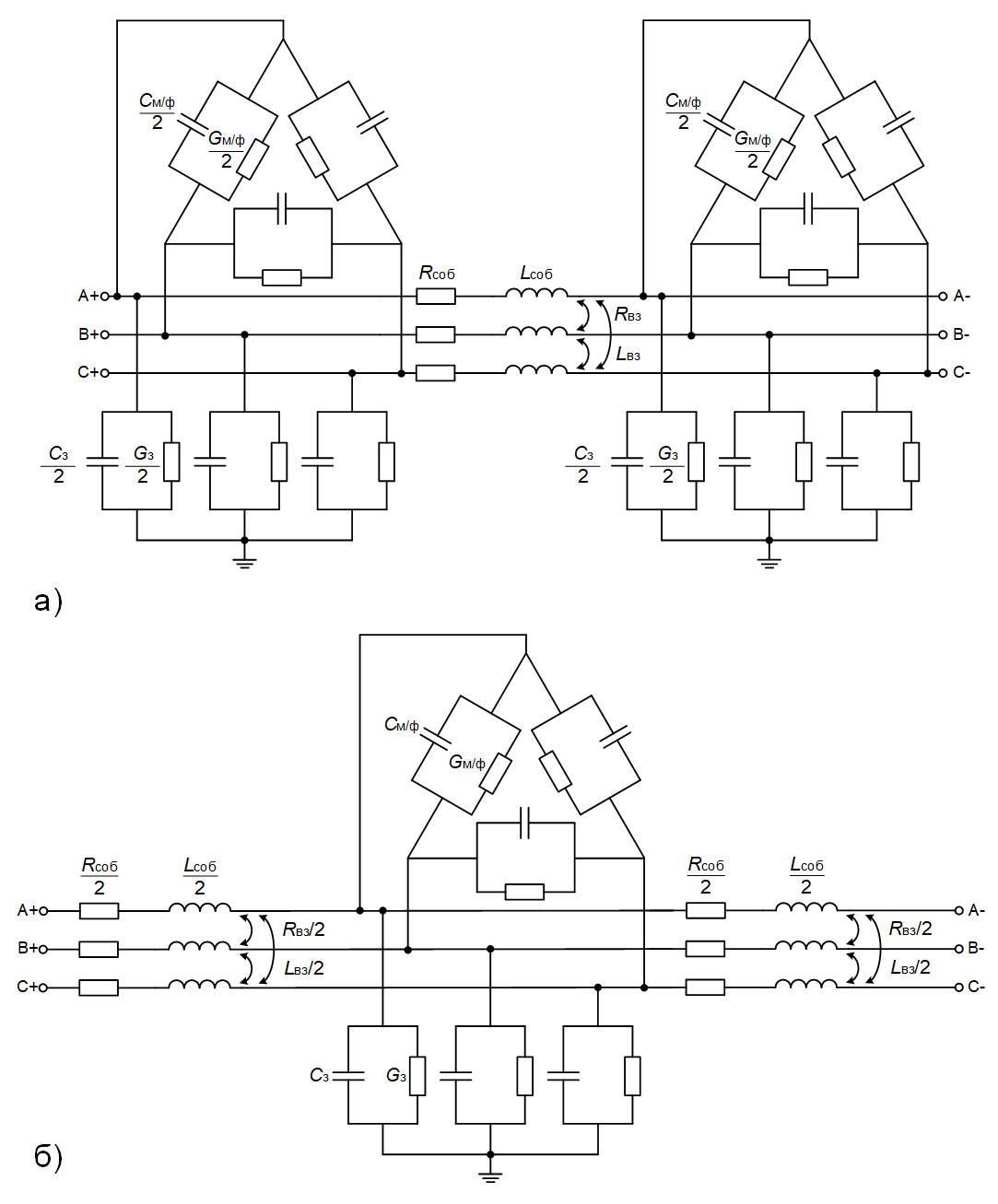
Fig. 1 П section (a) and T section (b) equivalent circuits of a three-phase PTL with lumped parameters#
The following parameters of the equivalent circuit are shown in Fig. 1:
R_{own}$ – the phase wire’s own active resistance, reflecting heating losses;
\(L_{own}\) – self-inductance of the phase wire, reflecting the self-inductance of the conductor;
\(R_{вз}\) - mutual active resistance of the phase wire, which occurs when taking into account the current return circuit through the ground;
Note
This value reflects the conditional distribution of active losses between phases. It is not directly related to losses in the phase conductors, but is the result of a mathematical transformation of the three-phase PTL model (for more details, see [2]).
\(L_{вз}\) – mutual inductance of the phase wire, reflecting the mutual inductance between the phase wires;
\(C_{м/ф}\) – the capacitance between the phases of the PTL, which causes displacement currents between the phase wires;
\(C_з\) – capacitance between the phase wire and the ground, causing leakage currents to the ground;
\(G_{m/f}\) – active conductivity between the phases of a PTL, causing leakage currents through the air gap;
Note
Leakage currents in this case are caused by the presence of moisture and contaminants in the air gap between the phase wires. If weather conditions are not taken into account in the modeling, \(G_{m/f}=0\) can be assumed.>
\(G_з\) – active conductivity between the phase conductor and the ground, which causes losses due to corona discharge and leakage currents through insulator strings.
Note
According to [1], corona discharge losses are generally taken into account when modeling PTL with a nominal voltage of 330 [kV] or higher. For 110 [kV] and 220 [kV] PTL, minimum wire cross-sections are established to reduce corona losses. If the PTL is constructed using wire with this or a larger cross-section, corona losses may be ignored. In this regard, the property Conductance matrix per unit length, [S/km] can be included in calculations or excluded from them using the property Enable conductance.
The procedure for calculating the parameters of the equivalent circuit of a power transmission line is described in the article “The procedure for calculating the specific parameters of three-phase power transmission line models”
The properties of the block Active resistance matrix per unit length, [Ohm/km], Inductance matrix per unit length, [H/km], Capacitance matrix per unit length, [F/km], Matrix of linear active admittances, [S/km] must be specified as 3 by 3 matrices with the following structure (using the example of the property Active resistance matrix per unit length, [Ohm/km]) (1):
where:
\(R_{aa},R_{bb},R_{cc}\) – own active resistances of phase A, B and C, respectively;
\(R_{ab},R_{bc},R_{ca}\) – взаимные активные сопротивления фаз A и B, B и C, C и A соответственно.
To ensure correct calculations when specifying matrices, it is necessary to adhere to several rules:
The diagonal elements (in the matrix (1) \(R_{aa},R_{bb},R_{cc}\)) must be non-negative.
The off-diagonal elements of the matrix must be pairwise equal, since they belong to the same phases (for the matrix (1) this means that \(R_{ab}=R_{ba},R_{bc}=R_{cb},R_{ca}=R_{ac}\)).
For the matrices of capacitances C and active conductivities G, it is recommended to set the off-diagonal elements as negative, which is related to the calculations of the parameters (more details[2]).
From the user-specified parameters of the linear capacity matrix, the parameters \(С_{м/ф}\) and \(С_з\) are calculated in the block:
The value of \(С_{м/ф}\) for a pair of phases is taken to be equal to the off-diagonal element with the opposite sign. For example, for phases A and B: \(С_{м/ф,ab}=-C_{ab}\)
The value of \(С_з\) for a phase is defined as the sum of all elements in the i-th row of the matrix. For example, for phase B: \(C_{з,b}=C_{ba}+C_{bb}+C_{bc}\)
Note
The parameters \(G_{м/ф}\) and \(G_з\) are calculated similarly.
Параметры П-образной схемы замещения рассчитываются по формулам (2), (3), (4), (5), (6), (7), (8) [1]:
The parameters of the T section equivalent circuit are calculated using the formulas (9), (10), (11), (12), (13), (14), (15) :
where:
\(r, l, g, c\) – linear values of active resistance, inductance, active conductivity, and capacitance;
\(\omega=2\cdot \pi \cdot f\) – angular frequency, which is calculated for the user-specified base frequency \(f\);
\(z,y\) – linear complex series resistance and transverse conductivity;
\(Z_в\) – wave resistance;
\(\gamma\) – propagation constant;
\(L_{секции}=L_{ЛЭП}/n_{секций}\) – длина секции, которая рассчитывается из заданных пользователем длины линии \(L_{ЛЭП}\) и количества секций \(n_{секций}\);
\(R, L, G, C\) – values of active resistance, inductance, active conductivity and capacitance, taking into account their uniform distribution along the length of the line.
Note
The calculated parameters \(R, L, G, C\) will be correct when the power supply frequency is close to the base frequency. If the power supply frequency deviates significantly, it is recommended to clarify the value of the corresponding property.
1. Properties#
Property |
Default Value |
Description |
Units of measurement |
|---|---|---|---|
50.0 |
- |
Hz |
|
1 |
- |
- |
|
Line length |
100.0 |
- |
km |
Section model: |
Pi section |
- |
- |
<0.349;0.0473;0.0475>_<0.0473;0.348;0.0473>_<0.0475;0.0473;0.349> |
- |
Ohm/km |
|
<2.423e-3;1.08e-3;1.1e-3>_<1.08e-3;2.425e-3;1.08e-3>_<1.1e-3;1.08e-3;2.423e-3> |
- |
H/km |
|
<7.25e-9;-1.42e-9;-1.47e-9>_<-1.42e-9;7.06e-9;-1.42e-9>_<-1.47e-9;-1.42e-9;7.25e-9> |
- |
F/km |
|
Off |
- |
- |
|
Conductance matrix per unit length, available when selecting |
<6.6e-6;0.0;0.0>_<0.0;6.6e-6;0.0>_<0.0;0.0;6.6e-6> |
- |
S/km |
2. Inputs and outputs#
Parameters |
Input/Output |
Description |
Units of measurement |
Port type |
|---|---|---|---|---|
A+ |
Input |
- |
- |
Electronics |
B+ |
Input |
- |
- |
Electronics |
C+ |
Input |
- |
- |
Electronics |
A- |
Output |
- |
- |
Electronics |
B- |
Output |
- |
- |
Electronics |
C- |
Output |
- |
- |
Electronics |
In order to see the connection capabilities of the block, you need to go to page Description of block ports