

Two way directional valve (P)#
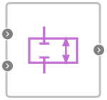
Block appearance in REPEAT VISION#
The Two way directional valve (P) unit describes the flow of gas through the valve section, which is controlled by an external signal. The external signal supplied through the port takes on the values in the range from 0 to 1
Valve opening can be parameterized linearly or using tabular data.
If Cross area calculation method is set to Linear, the hole area is determined by the formula (1) :
where:
\(A_{отв.}\) — hole area, [m\(^2\)];
S — rod position;
\(A_{leak}\) — leakage area when the valve is closed, [m\(^2\)];
\(A_{max}\) — maximum cross-sectional area of the valve, [m\(^2\)].
If Cross area calculation method is set to Table, the hole area is determined according to the stem position vector and the hole area vector by interpolation.
Parameters \(A_{leak}\) and \(A_{max}\) are defined according to the first and last element of the hole area vector.
Mass flow calculation
The block calculates the mass flow rate as (2):
where:
\(C_d\) – discharge coefficient;
\(S_r\) – area of the hole, [m\(^2\)];
S — cross-sectional area of ports A and B, [m\(^2\)];
\( ho\) – gas density, [kg/m\(^3\)];
p - gas pressure, [Pa];
\(\gamma\) - the adiabatic index.
Linearization of the equation for \(\frac{p_{out}}{p_{in}}\)>B\(_{lam}\) (3):
When the pressure ratio is less than the ratio \(\frac{p_{out}}{p_{in}}\) < \((\frac{2}{\gamma +1})^\frac {\gamma}{\gamma-1}\) the equation assumes (4):
Energy conservation law (5):
where:
\(\phi_А\) - energy flow at the input, [W];
\(\phi_В\) - energy flow at the output, [W].
1. Properties#
Property |
Default value |
Description |
Units of measurement |
|---|---|---|---|
Cross area calculation method: |
Linear |
- |
- |
Fraction zero signal |
0 |
- |
- |
Discharged coefficient |
0.64 |
- |
- |
Area port |
0.1 |
- |
m\(^2\) |
Leakage area, available when |
1e-10 |
- |
m\(^2\) |
Valve max area, available when |
1e-4 |
- |
m\(^2\) |
Smoothing factor, available when |
0.01 |
- |
- |
Fraction open vector, available when |
{0, 0.2, 0.4, 0.6, 0.8, 1.0} |
Field filling format: 0;0.2;0.4;0.6;0.8;1.0 |
m |
Valve cross area vector, available when |
{1e-10, 2e-05, 4e-05, 6e-5, 8e-5, 1e-4} |
Field filling format: 0;0.2;0.4;0.6;0.8;1.0 |
m\(^2\) |
Laminar flow pressure ratio |
0.999 |
- |
- |
2. Inputs and outputs#
Parameters |
Input/Output |
Description |
Units of measurement |
Port type |
|---|---|---|---|---|
Input |
Input |
- |
- |
Pneumatics |
Fraction |
Input |
- |
- |
Automation |
Output |
Output |
- |
- |
Pneumatics |
In order to see the connection capabilities of the block, you need to go to page Description of block ports