

Simplified synchronous machine#
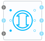
Block appearance in REPEAT VISION#
The Simplified synchronous machine block represents a simplified modelof a synchronous machine. The machine can be operated in generator or motorizedmode at the user’s option. In this block it is possible to select the input mechanicalquantity: mechanical power of the primary motor or its angular velocity(when selecting the generator mode), mechanical power of the mechanism connectedto the machine rotor or the angular velocity communicated to it (when selecting the drive mode).
This model is designed to consider electromechanical and someelectromagnetic transients at relatively small deviations fromthe rated machine speed. It is not intended to simulate transient processesduring machine starting, transition from engine to generator operation mode,short circuits close to the machine outputs.
This block is electrically a three-phase EMF source downstream of anelectrical active-inductive resistor. Depending on the selected mechanicalinput type, the method of setting the source frequency changes.The scattering inductances and armature reactions and the activeresistance of the stator winding are taken into account. The dampingcircuits are taken into account by an appropriate coefficient in the motion equation.
When choosing power as the mechanical output quantity, the source frequencywill be calculated according to the motion equation, which in thisimplementation has the following type (1) :
where:
\(\Delta\omega_{o.e}\) - the frequency deviation from the nominal frequency, [r.u.];
\(P_{mec}\) - input mechanical power, [W];
\(P_{el}\) - output active electric power of the generator, [W];
\(S_{rat}\) - full rated power of the generator, [VA];
\(K_D\) - damping coefficient, [r.u.];
\( T_{J} = \frac{\mathrm{J}\mathrm{ }\cdot \mathrm{\omega }_{0М}^{2}}{S_{\mathrm{r}\mathrm{a}\mathrm{t}}}\) - inertia constant, [s];
\(J\) - moment of inertia,
\(\omega _{0М}\) - synchronous mechanical frequency (calculated fromthe rated electrical frequency of the generator set in model parametersand the user-specified number of pole pairs according to the following formula (2) :
where:
\(\omega_{0}\) - synchronous electrical frequency, [rad/s];
\(f_0\) - synchronous electric frequency (nominal frequency of the generator), [Hz];
\(p\) - is the number of generator pole pairs, [rad/s].
Note
Данный способ задания входного механического воздействия необходим для использования с различными регуляторами и библиотекой Автоматика.
When frequency is selected as the mechanical input quantity,the source angular frequency will be specified as (3) :
where:
\( \mathrm{\omega }_{\mathrm{м}\mathrm{е}\mathrm{х}}\) - mechanical angular frequency of the prime mover, [rad/s];
\(p\) is the number of generator pole pairs.
Note
This method of specifying the input mechanical action is necessary for use with the Mechanics library.
1. Properties#
Property |
Default value |
Description |
Units of measurement |
|---|---|---|---|
Operation mode: |
Generator |
– |
– |
Type of mechanical input: |
Mechanical power |
– |
– |
Nominal apparent power |
200e6 |
– |
VA |
Nominal RMS phase-to-phase voltage |
15.75e3 |
– |
V |
Nominal frequency |
50 |
– |
Hz |
Inertia |
5.275e3 |
– |
kg \(\cdot\) m\(^2\) |
Damping factor |
0 |
– |
– |
Pairs of poles |
20 |
– |
– |
Resistance of stator winding |
0.0204 |
– |
Ohm |
Inductance of stator winding |
0.8104e-3 |
– |
H |
Initial frequency deviation |
10 |
– |
% |
Initial electrical angular position of the rotor |
0 |
– |
Electrical degrees |
Initial values of phase currents |
7.5e3;7.5e3;7.5e3 |
Data structure: \( I_{0A};\mathrm{I}_{0B};\mathrm{I}_{0C}/\) |
A |
2. Inputs and outputs#
Parameters |
Input/Output |
Description |
Units of measurement |
Port type |
|---|---|---|---|---|
Mechanical input |
Input |
– |
– |
Automation |
Neutral |
Input |
– |
– |
Electronics |
RMS phase-to-phase EMF |
Input |
– |
V |
Automation |
A+ |
Output |
– |
– |
Electronics |
B+ |
Output |
– |
– |
Electronics |
C+ |
Output |
– |
– |
Electronics |
In order to see the connection capabilities of the block, you need to go to page Description of block ports