

Two-winding transformer#
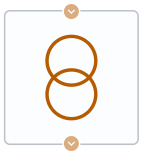
Block appearance in REPEAT VISION#
Note
When adding a block to the canvas, a window appears with a choice of the required configuration, which allows you to:
Select a ready-made template with settings for a specific brand of transformer;
Select customizable configuration
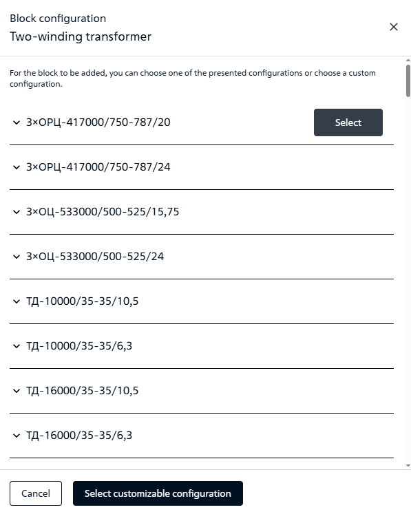
Configuration selection window#
The Two-winding transformer block is designed for conversionof AC voltage into another voltage system by means of electromagneticinduction in accordance with the set transformation ratio without frequency change.
Note
The conversion is non-ideal due to natural lossesin transformer steel and windings.
Equivalent circuit of the double-winding transformershown below (see Fig. 1) is suitable for simulation ofsteady-state modes and electromechanical transients:
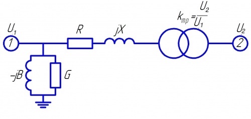
Fig. 1 Double-winding transformer equivalent circuit#
All values of the equivalent circuit parameters shall be calculated fromthe catalog data of the transformer and brought to its ratedvoltage (in case of step-up transformer, when the low voltage winding is primary, the valueof the rated voltage of the low side shall be specified in the block):
the active resistance of the transformer is determined on the basis of \(∆P_{sc}\) loss power obtained during the short-circuit experiment (1):
the impedance is determined on the basis of \(U_{sc}\) short-circuit voltage value determined during the short-circuit experiment and given as a percentage of the rated voltage (2):
reactance is determined on the basis of the total and activeresistances (3):
the active and reactive shunt resistances are calculated from catalog (4):
transformation factor (5):
1. Properties#
Property |
Default value |
Description |
Units of measurement |
|---|---|---|---|
Transformer rated power |
1 |
Rated power of transformer primary winding |
MVA |
Transformer ratio |
0.04 |
Rated transformation factor |
- |
Primary voltage |
10 |
Primary winding rated voltage |
kV |
Short-circuit voltage |
35 |
- |
% |
Short-circuit power losses |
7.5 |
- |
kW |
Incorporate no load power losses |
Off |
- |
- |
No load power losses |
43 |
idle run losses (losses in steel) |
kW |
No load current |
0.6 |
idle current as a percentage of the rated current of the primary winding |
% |
Fixed tap changer: |
No tap changer |
- |
- |
Positive tap number |
2 |
Available, when |
- |
Negative tap number |
-2 |
Available, when |
- |
Tap setting |
2.5 |
Available, when |
% |
Current step |
0 |
Available, when |
- |
2. Inputs and outputs#
Parameters |
Input/Output |
Description |
Units of measurement |
Port type |
|---|---|---|---|---|
Input |
Input |
- |
V |
Electrocity |
Transformer ratio |
Input |
Available, when |
- |
Автоматика |
Secondary voltage |
Output |
- |
V |
Electrocity |
In order to see the connection capabilities of the block, you need to go to page Description of block ports