

Relief Valve (TL)#
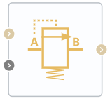
Block appearance in REPEAT VISION#
The Relief Valve (TL) block is a pressure relief valve in isothermal network. The valve remains closed when the monitored pressure drop is less than the set value, and if this value is reached or exceeded, the valve begins to open. Depending on the unit setting Opening pressure specification, the pressure set point is either the pressure drop between ports A and B or the pressure drop between port A and atmospheric pressure, i.e. the overpressure value in port A.
Depending on the user-selected value of Valve type and parametrization property, block can operate in the following ways:
Constant Drop Setpoint (set by property
Pressure drop set), or pressure setpoint (propertyPort A pressure set); linear dependence of the valve cross-section area on the actual design pressure drop;Pressure drop setpoint monitored through the Automation port>; linear dependence of the valve cross-section area on the actual design pressure drop;
Constant setpoint of pressure drop; tabular parameterization of the valve cross-section area by dependence on the design drop using interpolation for intermediate values;
Constant setpoint of pressure drop; tabular parametrization of liquid flow rate through the valve by dependence on the design drop using interpolation for intermediate values.
For valve operating options 1 and 2 the area of liquid flow through the valve is determined by the formula (1) :
where:
\(P_{norm}\) - normalized pressure;
\(A_{leak}\) - leakage area;
\(A_{max}\) - maximum area of the valve cross-section.
The normalized pressure \(P_{norm}\), that controls the valve opening area is calculated as follows (2) :
where:
\(P_{control}\) is the control drop (see above - either the drop between ports A and B or the pressure in port A);
\(P_{set}\) - pressure drop setpoint. Depending on the value of the parameter Valve type and parametrization (Constant or Controlled), this value is either set through the property of the block Pressure drop set, or takes signal values from port S;
\(P_{max}\) - maximum of pressure control range, numerically is the sum of pressure drop setpoint and control range (\(P_{max} = P_{set} + P_{range}\));
\(P_{range}\) - value of parameter Pressure regulation range.
The block retains mass so that (3):
This mass balance implies that the velocity increases as the area decreases and decreases when the flow discharges over a larger area. According to Bernoulli’s principle, this change in velocity results in a region of lower pressure in the hole and higher pressure in the expansion area. The resulting increase in pressure, called pressure recovery, depends on the pressure recovery loss ratio and the area ratio of the hole and port.
Mass flow rate calculation
The block calculates the mass flow rate as (4):
where:
\(C_d\) – discharge factor;
\(A_{orifice}\) – hole area;
\(A_{port}\) — cross-sectional area of ports A and B;
\(\barρ\) – average liquid density.
Pressure loss
Pressure loss describes a decrease in valve pressure due to a decrease in area. Pressure loss, \(PR_{loss}\) calculated as (5):
Critical pressure
Critical pressure drop, \(Δp_{crit}\) , is the pressure drop associated with the critical Reynolds number, \(Re_{crit}\), which is the transition point between laminar and turbulent liquid flow (6):
Law of conservation of energy (7):
where:
\(\phi_A\) - energy flow at the input, [W];
\(\phi_B\) - energy flow at the output, [W].
1. Properties#
Property |
Default Value |
Description |
Units of measurement |
|---|---|---|---|
Valve type and parametrization: |
Constant pressure drop, linear parametrization |
- |
- |
Opening pressure specification: |
Port pressure drop monitoring |
- |
- |
Pressure recovery, available by selecting |
Off |
- |
- |
Pressure drop set, available by selecting |
0 |
- |
Pa |
Port A pressure set, available by selecting |
0 |
- |
Pa |
Pressure regulation range, available by selecting |
100000 |
- |
Pa |
Maximum valve area, available by selecting |
0.0001 |
- |
m\(^2\) |
Leakage area, available by selecting |
1e-10 |
- |
m\(^2\) |
Port area, available by selecting |
0.1 |
- |
m\(^2\) |
Discharged coefficient, available by selecting |
0.64 |
- |
- |
Critical Reynolds number, available by selecting |
150.0 |
Reynolds number at which the transition from laminar flow mode to turbulent one occurs |
- |
Smoothing factor, available by selecting |
0.01 |
- |
- |
Pressure drop vector, available by selecting |
2e5, 4e5, 6e5, 8e5, 1e6, 1.2e6 |
- |
Pa |
Port A pressure vector, available by selecting |
2e5, 4e5, 6e5, 8e5, 1e6, 1.2e6 |
- |
Pa |
Valve open area vector, available by selecting |
1e-10, 2e-6, 4e-6, 6e-6, 8e-6, 1e-5 |
- |
m\(^2\) |
Flow vector, available by selecting |
1e-9, 3.6e-5, 8.9e-5, 1.5e-4, 2.3e-4, 3.1e-4 |
- |
m\(^3\)/s |
2. Inputs and outputs#
Parameters |
Input/Output |
Description |
Units of measurement |
Port type |
|---|---|---|---|---|
Input |
Input |
- |
- |
Thermohydraulics |
Pressure drop |
Input |
- |
Pa |
Automation |
Output |
Output |
- |
- |
Thermohydraulics |
In order to see the connection capabilities of the block, you need to go to page Description of block ports