

X-junction (TL)#

Block appearance in REPEAT VISION#
The X-junction (TL) block simulates the junction of four branches of the hydraulic network at an angle of 90\(^о\).
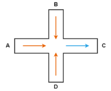
Fig. 1 Flow converging to vertex C#
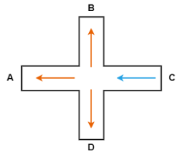
Fig. 2 Flow diverging from vertex C#
Hint
The AC branch is the main one, the BD branch is the side one.
1. Calculation of loss coefficients#
With this setting, the user directly sets dimensionless loss coefficients for converging and diverging, perpendicular and counter flows:
divLossCoef– when three flows making part of an assembly merge into one common flow in the direction of the fourth vertex of the junction:
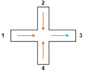
Fig. 3 Three flows making part of an assembly merge into one common flow in the direction of the fourth junction vertex#
convLossCoef– when an incoming flow on one of the vertices diverges into three flows towards the other three vertices:
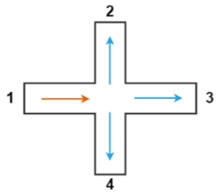
Fig. 4 The incoming flow on one of the vertices diverges into three flows towards the other three vertices#
perpLossCoef- when the two flows entering the assembly are perpendicular and the two outgoing flows are perpendicular to the incoming ones and each other:
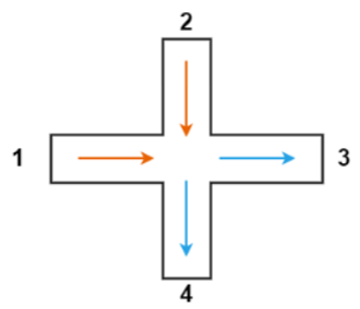
Fig. 5 The two flows entering the assembly are perpendicular and the two outgoing flows are perpendicular to the incoming ones and each other#
collLossCoef- for the case when two flows entering the assembly are opposite, and two outgoing flows form an angle of 90\(^о\):
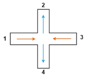
Fig. 6 The two flows entering the assembly are opposite, and the two outgoing flows form an angle of 90° with the incoming flow#
Mass conservation equation(1) :
Pressure drop calculation (2) :
where:
\(I=A, B, C, D\);
\(A_i\) – cross-sectional area of branch I, [m\(^2\)];
\(K_i\) – dimensionless loss factors on branch I;
\(I_i\) – liquid inertia on branch I;
\(m_i\) – mass flow rate of liquid through port I, [kg/s].
\(m_{thresh}\) – threshold flow rate, below which the flow is considered stagnant and cannot be defined as converging or diverging. Calculated using the following formula (3) :
where:
\(A_{min}\) – minimum area of the side and main branches, [m\(^2\)];
\( ho\) – liquid density, [kg/m\(^3\)];
\( u\) – liquid kinematic viscosity, [mm\(^2\)/s].
Calculation of inertia (4), (5), (6), (7) :
2. Properties#
Property |
Default Value |
Description |
Units of measurement |
|---|---|---|---|
Main branch area |
0.01 |
- |
m\(^2\) |
Side branch area |
0.01 |
- |
m\(^2\) |
Critical Reynolds number |
150.0 |
- |
- |
Loss coefficient for divergence flow |
1.12 |
- |
- |
Loss coefficient for convergence flow |
1.12 |
- |
- |
Loss coefficient for perpendicular flow |
1.12 |
- |
- |
Loss coefficient for colliding flow |
1.12 |
- |
- |
3. Inputs and outputs#
Parameters |
Input/Output |
Description |
Units of measurement |
Port type |
|---|---|---|---|---|
Port A |
Input |
- |
- |
Thermohydraulics |
Port B |
Input |
- |
- |
Thermohydraulics |
Port С |
Input |
- |
- |
Thermohydraulics |
Port D |
Input |
- |
- |
Thermohydraulics |
In order to see the connection capabilities of the block, you need to go to page Description of block ports