

NTU heat transfer#
Block appearance in REPEAT VISION#
The block allows modeling heat exchange between two environments using the NTU method.
In combination with the Heat exchanger interface (TL) block, it allows modeling heat exchangers calculated using the NTU method.
Note
In the block settings, the user can select the required Heat exchanger type.
Heat flow by the method NTU (1) :
where:
\(\epsilon\) – heat exchanger efficiency coefficient;
\(C_{min}\) – minimum value of \(\dot m_1 \cdot C_{p1}\) and \(\dot m_2 \cdot C_{p2}\), [W/℃];
\(\dot m_1, \dot m_2\) – mass flow rate of medium 1 and 2, [kg/s];
\(C_{p1},C_{p2}\) – specific heat capacity of environment 1 and 2 [\(\frac{J}{kg \cdot ℃}\)];
\(T_{вх}^{ср1},T_{вх}^{ср2}\) – температура среды 1 и 2 на входе в теплообменник, [℃].
Heat exchanger efficiency (2):
where:
\(Q\) – actual heat flow, [W];
\(Q_{max}\) - maximum possible heat flow, [W].
Formula for calculating the efficiency of a heat exchanger for different mutual movement of the coolant [1]
Pipe-in-pipe heat exchanger (Fig. 1):
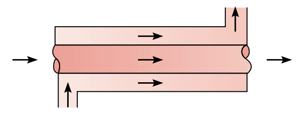
where:
NTU - number of heat transfer units;
\(C_{отн} = \frac{C_{мин}}{C_{макс}}\).
For the case \(C_{rel}\) = 1 (5) :
Shell-and-tube heat exchanger (Fig. 2):
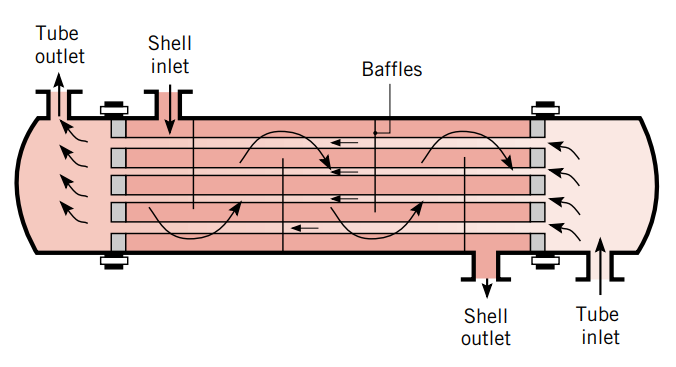
For the case of one flow of the medium in the housing and 2, 4… flows of the medium in the pipes (6) : [1]
Cross-flow heat exchanger (Fig. 3):
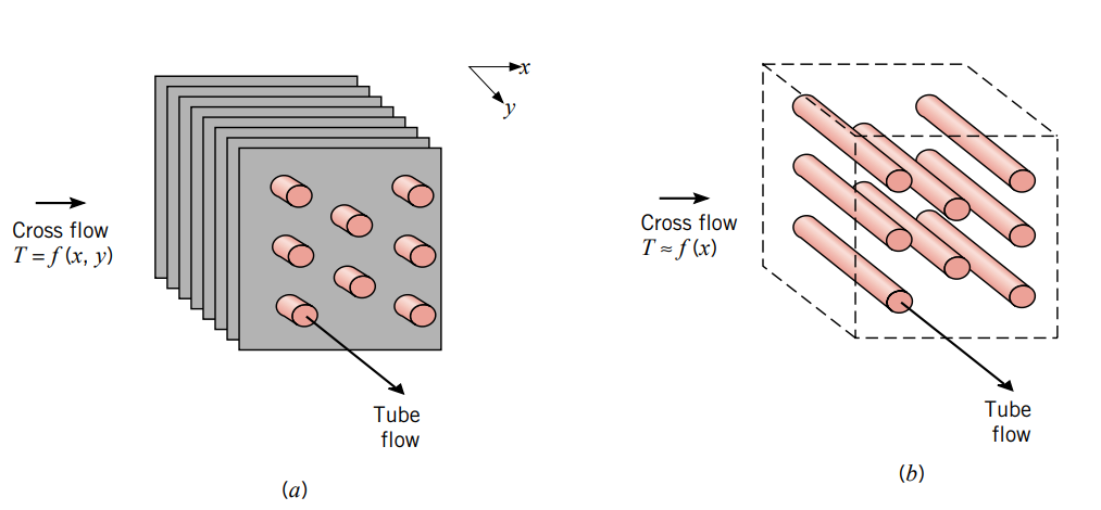
Fig. 3 Cross-flow heat exchangers [1]
a) Finned (both media do not mix)
b) Non-finned (one liquid mixes, the other does not)#
Number of heat transfer units (12) :
where \(R_{total}\) is the total thermal resistance between two liquids without taking into account the thermal conductivity of the liquids, [℃/W], (13) :
where:
\(\alpha_1, \alpha_2\) – heat transfer coefficients for environment 1 and 2, [\(\frac{W}{m^2 \cdot ℃}\)];
\(A_{ср1}, A_{ср2}\) – area of heat exchange surface for environment 1 and 2, [m\(^2\)];
\(R_{f1},R_{f2}\) – surface contamination coefficients for environments 1 and 2, [\(\frac{m^2 \cdot ℃}{W}\)];
\(R_{st}\) – thermal resistance of the wall, [\(\frac{℃}{W}\)].
1. Properties#
Property |
Default Value |
Description |
Units of measurement |
|---|---|---|---|
Heat exchanger type: |
Parallel or counter flow |
- |
- |
Number of shell passes, available when selecting |
1 |
- |
pieces |
Cross flow type: |
Both fluids mixed |
- |
- |
Number of heat transfer unit vector, available when selecting |
0.5;1.0;2.0;3.0;4.0;5.0; |
- |
- |
Thermal capacity ratio vector, available when selecting |
0.0;0.25;0.5;0.75;1.0; |
- |
- |
Effectiveness table, available when selecting |
\u003C0.3;0.3;0.3;0.3;0.3\u003E_ |
- |
- |
Wall thermal resistance |
1.5E-4 |
- |
°C/W |
Heat transfer surface area (medium 1) |
0.01 |
- |
m\(^2\) |
Fouling factor (medium 1) |
1.0E-4 |
- |
°С·m²/W |
Minimum fluid wall heat transfer coefficient (medium 1) |
5.0 |
- |
W/(m² ·°С) |
Heat transfer surface area (medium 2) |
0.01 |
- |
m\(^2\) |
Fouling factor (medium 2) |
1.0E-4 |
- |
°С·m²/W |
Minimum fluid wall heat transfer coefficient (medium 2) |
5.0 |
- |
W/(m² ·°С) |
2. Inputs and outputs#
Parameters |
Input/Output |
Description |
Units of measurement |
Port type |
|---|---|---|---|---|
Heat port (medium 1) |
Input |
- |
- |
Heat exchange |
Heat port (medium 2) |
Input |
- |
- |
Heat exchange |
Thermal capacity rate (medium 1) |
Input |
- |
W/°C |
Automation |
Heat transfer coefficient (medium 1) |
Input |
- |
W/(m² ·°С) |
Automation |
Thermal capacity rate (medium 2) |
Input |
- |
W/°C |
Automation |
Heat transfer coefficient (medium 2) |
Input |
- |
W/(m² ·°С) |
Automation |
In order to see the connection capabilities of the block, you need to go to page Description of block ports