

Variable transmission drive#
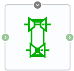
Block appearance in REPEAT VISION#
This block simulates a transmission that dynamically transmits motion and torque between two elastically coupled transmission shafts - the driving shaft and the driven shaft.
The user can specify whether the driven shaft rotates in the same or opposite direction to the input shaft. If the input and output shafts rotate in the same direction, the angular velocities \(ω_F\) and \(ω_B\) have the same sign. If the rotation occurs in opposite directions, the signs of \(ω_F\) and \(ω_B\) are different.
With a positive gear ratio, the direction of rotation of the driven shaft corresponds to the user-specified direction. With a negative gear ratio, the driven shaft rotates in the opposite direction to the direction of rotation of the drive shaft. At zero gear ratio, the shafts are disconnected and there is no transmission of torque between them.
An ideal transmission without relative displacement \(\phi\) imposes a relationship between the angular velocities of the driving and driven shafts through a variable gear ratio \(g(t)\) (1) :
When taking into account the elastic connection (stiffness and damping > 0), a displacement \(\phi\) occurs, which models the compliance of the transmission (2) :
where:
\(M_{leading}\) – torque on the leading shaft;
\(M_{driven}\) – torque on the driven shaft;
\(M_{losses}\) – losses during torque transmission;
\(d\) – transmission damping, [\(\frac{N\cdot m \cdot s}{rad}\)];
\(k\) – transmission stiffness, [\(\frac{N \cdotm}{rad}\)].
1. Accounting for losses#
When the Calculate losses \(M_{losses}
eq\) 0 property is enabled, losses are calculated relative to Efficiency. For a more detailed description of the loss calculation, please refer to the Loss Calculation page.
Note
The full calculation of the coupling Efficiency occurs if the transmitted power exceeds the specified threshold value \(p_{prg}\). Otherwise, for numerical stability, the Efficiency is assumed to be equal to unity.
2. Properties#
Property |
Default Value |
Description |
Units of measurement |
|---|---|---|---|
Co-directional base and follower shafts rotation |
Off |
- |
- |
Transmission damping |
3000 |
- |
N·m/(rad/s) |
Transmission stiffness |
3000 |
- |
N·m/rad |
Off |
- |
- |
|
Efficiency, available when |
0.8 |
- |
- |
Power threshold, available when |
0.001 |
- |
- |
3. Inputs and outputs#
Parameters |
Input/Output |
Description |
Units of measurement |
Port type |
|---|---|---|---|---|
Gear ratio |
Input |
- |
- |
Automation |
Base shaft |
Input |
- |
- |
Rotational motion |
Follower shaft |
Output |
- |
- |
Rotational motion |
In order to see the connection capabilities of the block, you need to go to page Description of block ports