

Poppet valve (TL)#
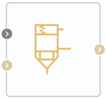
Block appearance in REPEAT VISION#
The Poppet valve (TL) block is a flow control valve in a thermal hydraulic network.
Depending on the specified value of the Seat and poppet geometry property, the user can select the following valve configuration options:
Diameter of a spherical plate, [m];
Seat orifice diameter, [m];
Seat cone angle, \(^о\);
Offset, [m].
Conical seat, cylindrical stem. For this type of valve the user can set the following parameters:
Diameter of cylindrical rod, [m];
Seat cone angle, \(^о\);
Offset, [m].
Sharp-edged seat, ball poppet. For this type of valve, the user can set the following parameters:
Diameter of a spherical plate, [m];
Seat orifice diameter, [m];
Offset, [m].
For the valve configuration Conical seat, ball poppet, the valve flow area is defined as (1):
where the parameter \(G_{conical}\) is defined as (2):
Maximum distance between valve seat and plate, [m] (3):
where:
\(r_B\) – radius of a spherical plate, [m];
\(r_O\) – valve seat radius, [m];
\( heta\) – angle of the conical valve seat, \(^o\);
h – distance between valve seat and valve plate, [m].
For valve configuration Conical seat, cylindrical stem valve flow area is determined by the formula (4):
where:
h - distance between cylinder and seat, [m];
\(\theta\) - inclination angle of the seat cone, [rad];
d\(_s\) - diameter of cylindrical valve, [m];
A\(_{leak}\) - leakage area, [m\(^2\)].
The cross-section area of the valve is limited by the maximum displacement h\(_{max}\) (5):
For valve configuration Conical seat, cylindrical stem the cross-sectional area of the valve is defined as (6):
where the parameter \(G_{sharp}\) is defined as (7):
Maximum distance between valve seat and plate, [m] (8):
where:
\(r_B\) – radius of a spherical plate, [m];
\(r_O\) – valve seat radius, [m];
h – distance between valve seat and valve plate, [m].
Calculating the distance between the saddle and the plate
For all valve configurations considered, the distance h between the seat and the plate is determined as follows (9):
where:
S – plate position signal, [m];
Note
Transmitted via the Automation port
\(S_{min}\) – Offset, [m].
Saturation of the valve cross-sectional area
For all the valve configurations considered, saturation of the valve cross-sectional area occurs both on the right and on the left.
For any stem displacement, which is greater than \(h_{max}\) , \(A_{open}\) is the sum of the maximum cross-section of valve and the leakage area (10):
Equation of mass flow rate
Law of conservation of mass (11):
The mass flow rate through the valve is calculated using the following formula (12):
where:
С\(_d\) - loss coefficient at pressure recovery;
A\(_{valve}\) - current cross-section area of the valve, [m\(^2\)];
A\(_{port}\) - cross-section area of flow, [m\(^2\)];
\(\bar ho\) - average density of liquid, [kg/\(m^3\)];
\(\Delta p\) - is the pressure drop at valve, [Pa].
Critical pressure drop \(\Delta p_{crit}\) is the pressure drop associated with the critical Reynolds number, the point of transition of the flow mode from laminar to turbulent (6):
Pressure decrease describes the pressure decrease in the valve when the valve cross-section area is decreased.
PR\(_{loss}\) is calculated using the following formula (7):
Pressure recovery describes a positive pressure change in the valve when the area increases.
Law of conservation of energy (15):
where:
\(\phi_А\) - energy flow at the input, [W];
\(\phi_B\) - energy flow at the output, [W].
1. Properties#
Property |
Default value |
Description |
Units of measurement |
|---|---|---|---|
Seat and poppet geometry: |
Conical seat, ball poppet |
- |
- |
Ball diameter, available when |
0.01 |
- |
m |
Seat orifice diameter, available when |
0.007 |
- |
m |
0.01 |
- |
m |
|
Seat cone angle |
120.0 |
- |
\(^о\) |
Leakage area |
1.0e-10 |
- |
m\(^2\) |
Port area |
0.1 |
- |
m\(^2\) |
Discharge coefficient |
0.64 |
- |
- |
Critical Reynolds number |
150.0 |
The Reynolds number at which the transition from laminar to turbulent flow occurs |
- |
2. Inputs and outputs#
Parameters |
Input/Output |
Description |
Units of measurement |
Port type |
|---|---|---|---|---|
Displacement |
Input |
- |
m |
Automation |
Input |
Input |
- |
- |
Thermohydraulics |
Output |
Output |
- |
- |
Thermohydraulics |
In order to see the connection capabilities of the block, you need to go to page Description of block ports