

Wall#
Block appearance in REPEAT VISION#
The Wall block simulates the process of heat transfer through a wall of flat or cylindrical geometry.
The wall is divided into n parts (see Fig. 1 and Fig. 2) in accordance with the specified block property, each part of the division has a mass and its own thermophysical properties.
The maximum amount of parts is 100.
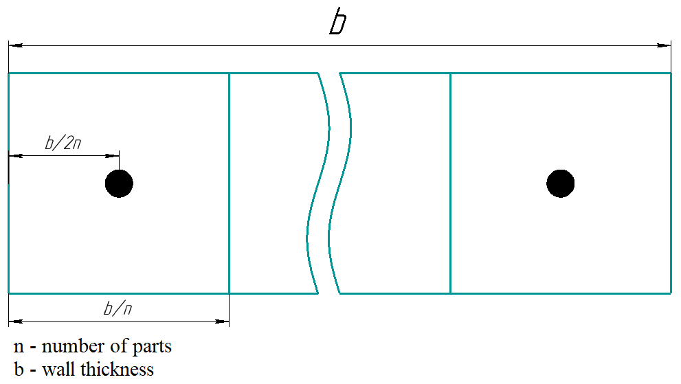
Fig. 1 Wall segmentation diagram#
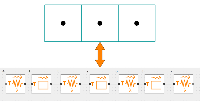
Fig. 2 - Wall divided into 3 segments and equivalent model from Heat exchange library blocks#
Heat flow in wall
Heat flow in flat wall (1):
where:
k - material thermal conductivity factor;
F - heat exchange surface area;
b - wall thickness;
\(T_1\) - temperature of the previous design point;
\(T_2\) - temperature of the next design point.
Heat flow in cylindrical wall (2):
where:
L - pipe length;
\(d_{out}\) - outer diameter of the pipe;
\(d_{in}\) - internal diameter of the pipe.
Segment temperatures
Segment temperatures are calculated according to the following equation (3):
where:
Q - heat flux;
c - specific heat capacity;
m - weight;
T - segment temperature;
t - time.
Thermophysical properties
The material properties (heat capacity, thermal conductivity) for each cell can be set constant, or determined depending on the temperature.
Specific heat capacity
Constant - the constant specific heat capacity set by the user in the “Specific heat capacity” field is used
Table of values - the specific heat capacity obtained based on a linear dependence built from the values entered by the user in “Specific heat capacity curve” and “Temperature curve” fields is used.
Material - the heat capacity is used according to the selected material in the associated block Materials properties.
Thermal conductivity
Constant - the user-defined thermal conductivity is used in “Thermal conductivity” field.
Table of values - the thermal conductivity obtained based on linear dependence built from the values entered by the user in “Thermal conductivity curve” and “Temperature curve” fields is used.
Material - the thermal conductivity according to the selected material in the associated block Materials Properties is used.
When calculating thermal conductivity, the average temperature is used:
For a flat wall (4) :
For a cylindrical wall (5) :
1. Properties#
Property |
Default value |
Description |
Units of measurement |
|---|---|---|---|
Number of parts |
2 |
– |
– |
Mass |
10.0 |
– |
kg |
Initial temperature |
20.0 |
– |
°С |
Wall geometry type: |
Plane |
– |
– |
Surface area, available when selecting |
10.0 |
– |
m\(^2\) |
Wall thickness, available when selecting |
0.02 |
– |
m |
Inner diameter, available when selecting |
0.02 |
– |
m |
Outer diameter, available when selecting |
0.05 |
– |
m |
Length, available when selecting |
10.0 |
– |
m |
Conductivity type: |
Constant |
– |
– |
Thermal conductivity, available when selecting |
1.7 |
– |
W/(m \(\cdot\) К) |
Thermal conductivity curve, available when selecting |
401.9;391.5;385.4;376.9; |
– |
W/(m \(\cdot\) К) |
Temperature curve, available when selecting |
26.85;126.85;226.85;326.85; |
– |
°С |
Specific heat type: |
Constant |
– |
- |
Specific heat capacity, available when selecting |
840.0 |
– |
J/(kg \(\cdot\) К) |
Specific heat capacity curve, available when selecting |
903.7; 951.3; 991.8; 1036.7 |
– |
J/(kg \(\cdot\) К) |
Temperature curve, available when selecting |
26.85; 126.85; 226.85; 326.85 |
– |
°С |
Material property, available when selecting |
– |
– |
– |
2. Inputs and outputs#
Parameters |
Input/output |
Description |
Units of measurement |
Port type |
|---|---|---|---|---|
Input |
Input |
- |
- |
HeatExchange |
Output |
Output |
- |
- |
HeatExchange |
In order to see the connection capabilities of the block, you need to go to page Description of block ports