

Permanent magnet synchronous machine (dynamic model)#
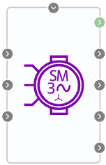
Block appearance in REPEAT VISION#
The Permanent magnet synchronous machine (dynamic model) block implements a generalized dynamic model of a synchronous electric machine with permanent magnets. The model assumes that the stator magnetic field induced by the permanent magnets is sinusoidal.
1. Properties#
Property |
Default value |
Description |
Units of measurement |
|---|---|---|---|
Armature resistance |
500e-3 |
– |
Ohm |
Inductance of the stator winding in the direct axis |
1e-3 |
– |
H |
Inductance of the stator winding in the quadrature axis |
1e-3 |
– |
H |
Flux linkage of magnets |
50e-3 |
Magnitude of the constant flux linkage induced in the stator winding by permanent magnets on one pair of poles |
Wb |
Friction factor |
100e-3 |
– |
N \(\cdot\) m \(\cdot\) s |
Moment of inertia |
1 |
Rotor moment of inertia |
kg \(\cdot\) m\(^2\) |
Number of pairs of magnetic poles |
1 |
Number of pairs of magnetic poles for stator winding |
– |
2. Inputs and outputs#
Parameters |
Input/Output |
Description |
Units of measurement |
Port type |
|---|---|---|---|---|
Ua |
Input |
Phase A voltage |
V |
Voltage |
Ub |
Input |
Phase B voltage |
V |
Voltage |
Uc |
Input |
Phase C voltage |
V |
Voltage |
External torque |
Input |
External resistance torque on the shaft |
N \(\cdot\) m |
Automation |
Angular frequency |
Output |
Angular frequency of shaft rotation |
rad/s |
Rotational motion |
Electromagnetic torque |
Output |
Torque on the shaft created by the electromagnetic field of the machine |
N \(\cdot\) m |
Automation |
Ia |
Output |
Phase A current |
A |
Automation |
Ib |
Output |
Phase B current |
A |
Automation |
Ic |
Output |
Phase C current |
A |
Automation |
In order to see the connection capabilities of the block, you need to go to page Description of block ports