

Orifice (IH)#
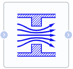
Block appearance in REPEAT VISION#
The Orifice (IH) block models the movement of a fluid flow through an appropriate local resistance.
Depending on the selected value of the Orifice parametrization property, the user can set the following block operation options:
Constant hole area, explicitly specifying the flow cross-sectional area as a block property;
Constant orifice area, tabular parameterization of fluid flow rate through the calculated value of pressure drop using interpolation for intermediate values;
Variable orifice area, calculation of the area (given below) of the flow cross-section according to the position of the regulating element (rod) closing part of the orifice, specified through the Automation port;
Variable orifice area, tabular parameterization of the flow cross-sectional area through the position of the control element (rod) specified via the Automation port using interpolation for intermediate values.
Calculation of the hole area (1) :
Note
This calculation is used only for item 3, since in item 1 the hole area is specified explicitly, in items 2 and 4 it is parameterized in a table.
where:
\(A_{orifice}\) – alculated hole area, [m\(^2\)];
\(A_{max}\) – maximum hole area, [m\(^2\)];
\(A_{leak}\) – leakage area, [m\(^2\)];
\(\Delta S\) – maximum rod travel, [m];
Signal – position of the rod, [m];
Note
Signal received through the automation port
Offset – rod offset for full close orifice, [m].
The unit retains mass so that
\(\dot m_{A}\:+\:\dot m_{B}\:=\:\rho\:\cdot \:\nu_{A}\:\cdot \:A_{A}\:+\: \rho\:\cdot \:\nu_{B}\:\cdot \:A_{B}\:=\:0\)
This mass balance implies that the velocity increases when the area decreases and decreases when the flow is discharged over a larger area. In accordance with Bernoulli’s principle, this change in velocity results in a region of lower bore pressure and higher expansion are pressure. The resulting increase in pressure, which is called pressure recovery, depends on the loss coefficient at restoring pressure and the ratio of the areas of the hole and port.
Mass flow calculation
The unit calculates the mass flow rate as follows:
where:
\(C_d\) – discharge coefficient;
\(A_{orifice}\) – area of the hole, [m\(^2\)];
\(A_{port}\) — cross-sectional area of ports A and B, [m\(^2\)];
\(\bar ρ\) – average liquid density, [kg/m\(^3\)].
Pressure loss
The pressure loss describes a decrease in pressure in the valve due to a decrease in area. Pressure loss, \(PR_{loss}\), is calculated as:
Critical pressure
Critical pressure differential, \(Δp_{crit}\) , is the pressure differential associated with the critical Reynolds number, \(Re_{crit}\) , which is the transition point between laminar and turbulent fluid flow:
\(\Delta p_{crit}\:=\:\frac{\Pi\:\cdot \:\bar \rho}{8\cdot A_{orifice}}\cdot \:(\frac{\nu\:\cdot Re_{crit}}{C_{d}})^2\)
1. Properties#
Property |
Default value |
Description |
Units of measurement |
|---|---|---|---|
Orifice parametrization: |
Constant area, set area |
- |
- |
Opening orientation: |
Positive |
- |
- |
Pressure recovery, available when |
On |
- |
- |
Port area, available when |
1.0E-4 |
- |
m\(^2\) |
Orifice area, available when |
5.0E-5 |
- |
m\(^2\) |
Rod offset for full close orifice, available when |
0.0 |
- |
m |
Maximum rod travel, available when |
0.005 |
- |
m |
Maximum area, available when |
1.0E-4 |
- |
m\(^2\) |
Leakage area, available when |
1.0E-11 |
- |
m\(^2\) |
Discharge coefficient, available when |
0.64 |
- |
- |
Smoothing factor, available when |
0.01 |
- |
- |
Critical Reynolds number, available when |
150.0 |
For calculation of the laminar flow |
- |
Pressure drop vector, available when |
-4000000.0; -3000000.0 -2000000.0; -1000000.0; -500000.0; 0.0; 500000.0; 1000000.0; 2000000.0; 3000000.0; 4000000.0 |
- |
Pa |
Flow vector, available when |
-2.44; -2.12; -1.68; -1.22; -0.84; 0.0; 0.85; 1.21; 1.7; 2.09; 2.41 |
- |
kg/s |
Rod position vector, available when |
0.0; 0.002; 0.004; 0.007; 0.017 |
- |
m |
Area orifice vector, available when |
1.0E-9; 2.0352E-7; 4.0736E-5; 1.1438E-4; 3.4356E-4 |
- |
m\(^2\) |
2. Inputs and outputs#
Parameters |
Input/Output |
Description |
Units of measurement |
Port type |
|---|---|---|---|---|
Input |
Input |
- |
- |
Isothermal hydraulics |
Input (Auto), available when |
Input |
- |
m |
Automation |
Output |
Output |
- |
- |
Isothermal hydraulics |
In order to see the connection capabilities of the block, you need to go to page Description of block ports
3. Примеры использования#
Для быстрого ознакомления с данным блоком откройте один из следующих ДЕМО-примеров:
[DEMO] Трубопровод с местным сопротивлением[DEMO] Поиск требуемого расхода в трубопроводной системе
С примером использования данного блока можно ознакомиться:
В практическом руководстве Determining the required water flow rate in a pipeline system
В практическом руководстве Basic methods of parametric studies