

M AEC#
Block appearance in REPEAT VISION#
Automatic excitation control (AEC) is a device that acts on the excitation system of synchronous machines to maintain the voltage in the electrical network at a given level.
This is a modern microprocessor-based regulator. Its primary operating mode is to regulate the station busbar voltage with a specified droop (1…5%) based on the generator’s reactive current. A PID voltage regulation law has been implemented, ensuring that in steady-state mode the voltage at the regulation point is practically equal to the setpoint. An automatic reduction of the voltage channel transmission coefficient in the frequency range of electromechanical oscillations is provided, which helps improve the damping of rotor oscillations.[1]
According to the diagram (see Fig. 1 below) the mathematical model of the regulator is written as (1) :
where:
\(X_T\) - transformer resistance, reduced to the nominal power and voltage of the generator;
\(K_T\) - the proportion of the block transformer resistance compensated in APV, [%];
\(\tau_1 = 20, \tau_2 = 50, \tau_3 = 20\) - delays of digital differentiators, [ms];
\(T_{If} = 150 [ms], T_{0f} = 2 [s], T_f=20[ms],T_{1f}=50[ms],T_{1U}=60[ms], T_{OKR}=0.5 [s]\).
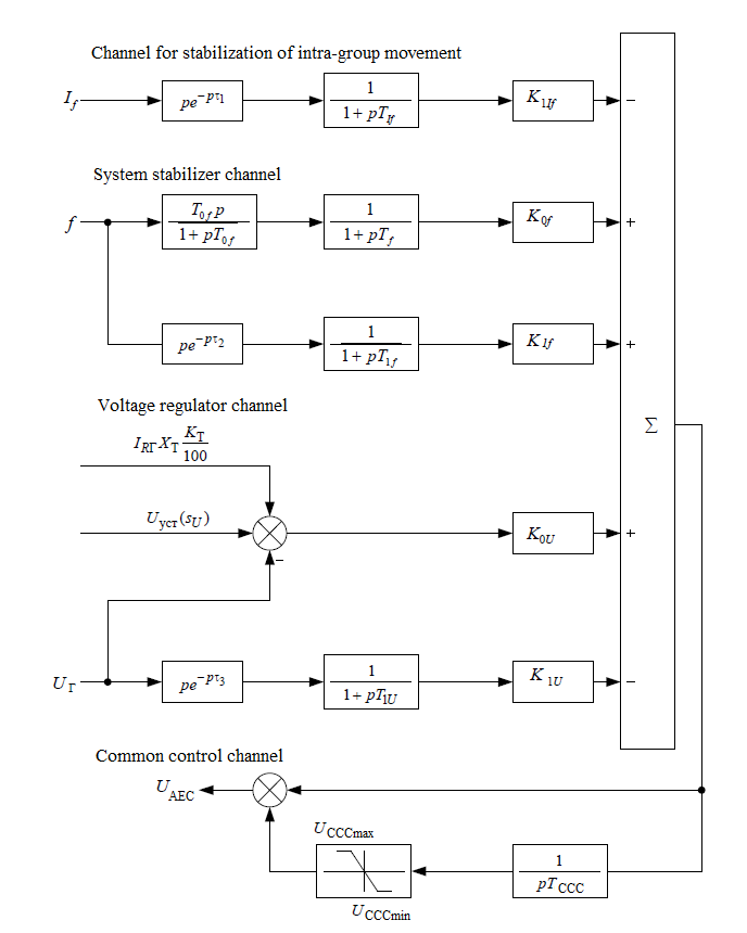
Fig. 1 Structural diagram of the digital excitation regulator M AEC#
where \(U_{OKRmax}=1.2, U_{OKRmin}=0.2\) - restrictions CCC
1. Properties#
Property |
Default Value |
Description |
Units of measurement |
|---|---|---|---|
Rotor current derivative gain |
5 |
– |
– |
Frequency gain |
2 |
– |
– |
Frequency derivative gain |
5 |
– |
– |
Voltage gain factor |
50 |
– |
– |
Voltage derivative gain |
5 |
– |
– |
Statism |
8 |
– |
% |
Transformer resistance |
0.2 |
– |
r.u. |
Maximum value of AEC voltage |
6 |
– |
V |
Minimum value of AEC voltage |
-6 |
– |
V |
2. Inputs and outputs#
Parameters |
Input/Output |
Description |
Units of measurement |
Port type |
|---|---|---|---|---|
Rotor current |
Input |
– |
A |
Automation |
Generator voltage frequency |
Input |
– |
Hz |
Automation |
Generator stator reactive current |
Input |
– |
A |
Automation |
Voltage setting |
Input |
– |
V |
Automation |
Generator voltage |
Input |
– |
V |
Automation |
Voltage AEC |
Output |
– |
V |
Automation |
In order to see the connection capabilities of the block, you need to go to page Description of block ports