

Four way two position hydraulic control valve (TL)#
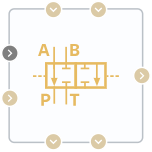
Block appearance in REPEAT VISION#
The block models the operation of a valve with four orifices in a thermal-hydraulic network. The valve is controlled by a single spool, the position of which is determined by the pressure drop in an external circuit and the signal at port S, which sets the setpoint for this pressure drop. The block has two inlets — A and B and two outlets — P and T, as well as an additional pair of ports from the external circuit — X and Y.
When ports are paired (AP, BP, AT, and BT), the block models fluid flow through four different orifices. Parameters affecting the flow through each orifice (spool stroke and maximum flow area) can be set identically for all four orifices or individually. The user also sets the initial spool offset (Valve close position parameter) relative to the position where the orifice is fully open.
The spool moves when the pressure drop between the controlled ports X and Y of the external circuit exceeds the setpoint value transmitted to the block through the automation port. Regulation stops if the actual pressure drop exceeds the maximum value, which is the sum of the setpoint pressure drop and the user-defined control range (parameter Pressure drop range control contour).
The spool movement increases linearly with the relative excess of the setpoint.
In the initial spool position, all orifices are closed, and as the spool moves, they begin to open sequentially according to the orifice diameter and the specified offset. If the spool continues to move after the orifice is fully open (within the specified maximum stroke), saturation occurs, and the flow through the valve orifice does not increase.
The flow area of each orifice depends linearly on the spool position and is described by the formula (1):
where:
\(S_{pos}\) - calculated parameter based on the signal from the automation port Valve close position, [m];
\(\Delta S\) is the parameter Valve travel, [m];
\(A_{max}\) is a parameter Valve max area, [m\(^2\)];
\(A_{leak}\) - parameter Leakage area, [m\(^2\)].
1. Properties#
Property |
Default Value |
Description |
Units of measurement |
|---|---|---|---|
Positive spool position open connections: |
PA and BT |
- |
- |
Negative spool position open connections: |
PA and BT |
- |
- |
Characteristics for area: |
Identical |
- |
- |
Linear |
- |
- |
|
1000.0 |
- |
Pa |
|
Valve travel PA |
0.05 |
Available, when |
m |
Valve travel PB |
0.05 |
Available, when |
m |
Valve travel AT |
0.05 |
Available, when |
m |
Valve travel BT |
0.05 |
Available, when |
m |
Valve max area PA |
1e-4 |
Available, when |
m\(^2\) |
Valve max area PB |
1e-4 |
Available, when |
m\(^2\) |
Valve max area AT |
1e-4 |
Available, when |
m\(^2\) |
Valve max area BT |
1e-4 |
Available, when |
m\(^2\) |
0.13 |
Available, when |
m |
|
1e-4 |
Available, when |
m\(^2\) |
|
1e-10 |
Available, when |
m\(^2\) |
|
Area port |
0.1 |
- |
m\(^2\) |
Discharge coefficient |
0.64 |
- |
- |
Reynolds critical numbers |
150.0 |
- |
- |
Smoothing factor |
0.01 |
- |
- |
Pressure recovery |
0.64 |
- |
- |
Valve close position PA |
5e-3 |
- |
m |
Valve close position PB |
5e-3 |
- |
m |
Valve close position AT |
5e-3 |
- |
m |
Valve close position BT |
5e-3 |
- |
m |
Valve travel |
0, 0.02, 0.04, 0.07, 0.017 |
Available, when |
m |
Valve cross area vector |
1e-06, 1e-05, 1e-04, 1e-3, 3e-3 |
Available, when |
m\(^2\) |
Valve travel PA |
0, 0.02, 0.04, 0.07, 0.017 |
Available, when |
m |
Valve travel PB |
0, 0.02, 0.04, 0.07, 0.017 |
Available, when |
m |
Valve travel AT |
0, 0.02, 0.04, 0.07, 0.017 |
Available, when |
m |
Valve travel BT |
0, 0.02, 0.04, 0.07, 0.017 |
Available, when |
m |
Valve cross area vector PA |
1e-06, 1e-05, 1e-04, 1e-3, 3e-3 |
Available, when |
m\(^2\) |
Valve cross area vector PB |
1e-06, 1e-05, 1e-04, 1e-3, 3e-3 |
Available, when |
m\(^2\) |
Valve cross area vector AT |
1e-06, 1e-05, 1e-04, 1e-3, 3e-3 |
Available, when |
m\(^2\) |
Valve cross area vector BT |
1e-06, 1e-05, 1e-04, 1e-3, 3e-3 |
Available, when |
m\(^2\) |
2. Inputs and outputs#
Parameters |
Input/Output |
Description |
Units of measurement |
Port type |
|---|---|---|---|---|
Port A |
Input |
- |
- |
Thermohydraulics |
Port B |
Input |
- |
- |
Thermohydraulics |
Pressure drop set |
Input |
- |
Pa |
Automation |
Control Port X |
Input |
- |
- |
Thermohydraulics |
Control Port Y |
Output |
- |
- |
Thermohydraulics |
Port P |
Output |
- |
- |
Thermohydraulics |
Port T |
Output |
- |
- |
Thermohydraulics |
In order to see the connection capabilities of the block, you need to go to page Description of block ports