

Generator#
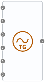
Block appearance in REPEAT VISION#
The block is a model of a synchronous generator.
Hint
It is recommended to use this block with the Controlled generator block from the Electrocity library
The connection is made using the Demux block. The output port of the block must be connected to the input port of the Demux block with 9 output ports, Fig. 1:
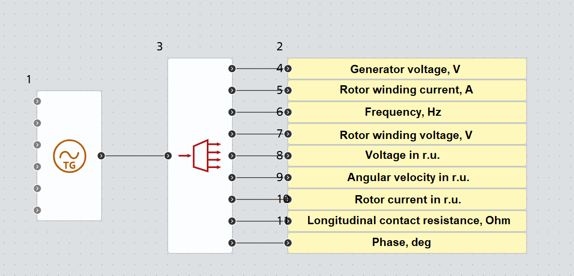
Fig. 1 Connection to the Demux block#
Output parameters from top to bottom:
The order of arrangement in Fig. 1 (top to bottom) |
Name |
Units of measurement |
|---|---|---|
1 |
Generator voltage |
V |
2 |
Rotor winding current |
А |
3 |
Frequency |
Hz |
4 |
Rotor winding voltage |
V |
5 |
Voltage |
r.u. |
6 |
Angular velocity |
r.u. |
7 |
Rotor current |
r.u. |
8 |
Longitudinal contact resistance |
Ohm |
9 |
Phase |
deg |
To connect to the Controlled generator unit, you need to connect it to ports 1, 3, 9 in the corresponding voltage, frequency and phase ports, Fig. 2:
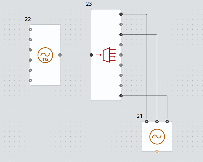
Fig. 2 Connection to the Controlled generator unit#
Hint
The remaining ports are required for setting up excitation system blocks and prime movers
The first input port is the port for input signals from the network. Connection is made using the Multiplexer block with 7 input ports, Fig. 3:
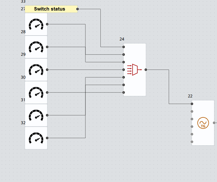
Fig. 3 Connection to the Multiplexer block#
Ports for the multiplexer from top to bottom:
The order of arrangement in Fig. 3 (top to bottom) |
Name |
Units of measurement |
|---|---|---|
1 |
Generator Breaker Status (0/1) |
- |
2 |
Real part of current |
А |
3 |
Imaginary part of current |
А |
4 |
Voltage |
V |
5 |
Active power |
W |
6 |
Reactive power |
VAr |
7 |
Network frequency |
r.u. |
All parameters are taken using sensors from the conductor and the bus immediately after the generator.
Ports Suppression (0/1), Loss of Excitation (0/1), Overload (0/1) are event ports.
Note
By default, it’s always set to 0. When set to 0, they don’t affect the block’s operation. When set to 1, they change the output parameters according to the event that occurred.
The Turbine power and Excitation voltage ports are primary for generator control and recommend connecting units from the Prime movers section for power and Excitation systems for voltage.
1. Properties#
Property |
Default Value |
Description |
Units of measurement |
|---|---|---|---|
Rated current of the rotor winding |
436 |
- |
А |
Open circuit voltage of the rotor winding |
70 |
- |
V |
Integrator Gain(1/Mechanical Time Constant) |
1/3.2 |
- |
- |
Rated voltage |
10.5 |
- |
kV |
Rated power |
7.5 |
- |
MW |
Rated power factor |
0.8 |
- |
- |
Damping factor |
0.2 |
- |
- |
Mechanical time constant |
3.2 |
- |
s |
Longitudinal transient reactivity |
0.28 |
- |
r.u. |
Rated current |
517 |
- |
А |
Longitudinal reactance |
1.61 |
- |
Ohm |
Rotor winding time constant |
4.9 |
- |
s |
Field blanking ratio |
20 |
- |
r.u. |
Rated rotation speed |
3000 |
- |
rpm |
2. Inputs and outputs#
Parameters |
Input/Output |
Description |
Units of measurement |
Port type |
|---|---|---|---|---|
Input parameters |
Input |
- |
- |
Automation |
Input |
- |
r.u. |
Automation |
|
Input |
- |
- |
Automation |
|
Input |
- |
V |
Automation |
|
Input |
- |
- |
Automation |
|
Input |
- |
- |
Automation |
|
Output parameters |
Output |
- |
- |
Automation |
In order to see the connection capabilities of the block, you need to go to page Description of block ports