

Transistor with reverse diode#
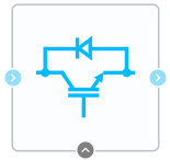
Block appearance in REPEAT VISION#
This unit is a simplified version of “Transistor - Reverse Diode” electrical circuit: in this circuit, resistance of diode and transistor activated state is the same and the direct bias voltage of the diode is not taken into account. The transistor is represented by a controlled circuit breaker, which opens at the control signal (G)> 0 (see Fig. 1 below).
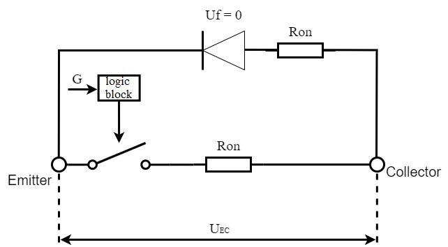
Fig. 1 Circuit of transistor with reverse diode#
The (Fig. 2) shows CVD of equivalent circuit (diode - reverse connection, so its activated state is in the 3rd quadrant):
Section 0-3 corresponds to the deactivated transistor state when the control command is g = 0: \(R_T\)=\(R_{clos.}\);
The open state of the diode illustrates section 1-2 when voltage drop across at transistor is less than the diode forward bias voltage: \(R_D\)=\(R_{int.}\);
Accordingly, in section 2-3 the diode is in the closed state and its resistance: \(R_D\)=\(R_{clos.}\);
Section 5-4 corresponds to the transistor state when the control command is g > 0: \(R_T\)=\(R_{int.}\).
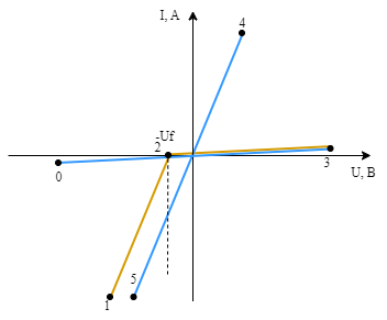
Fig. 2 FET CVD#
1. Properties#
Property |
Default Value |
Description |
Units of measurement |
|---|---|---|---|
Internal resistance |
0.001 |
- |
Ohm |
Turn-off resistance |
1e8 |
- |
Ohm |
On |
- |
- |
|
Snubber resistance, available when selecting |
1e6 |
- |
Ohm |
Snubber capacitance, available when selecting |
1e9 |
- |
F |
2. Inputs and outputs#
Parameters |
input/output |
Description |
Units of measurement |
Port type |
|---|---|---|---|---|
Control port |
Input |
- |
- |
Automation |
Collector |
Input |
- |
- |
Electronics |
Emitter |
Output |
- |
- |
Electronics |
In order to see the connection capabilities of the block, you need to go to page Description of block ports
See also
An example of using this block can be found in sections:
Electrical equipment subsection Power industry practical guide Implementation of DC insert and harmonic analysis of electric power system currents;
Electrical equipment subsection Power industry practical guide Simulation of static synchronous compensator based on voltage converter.